NJ1 el. & FREAK el. compact bike usage instructions
19
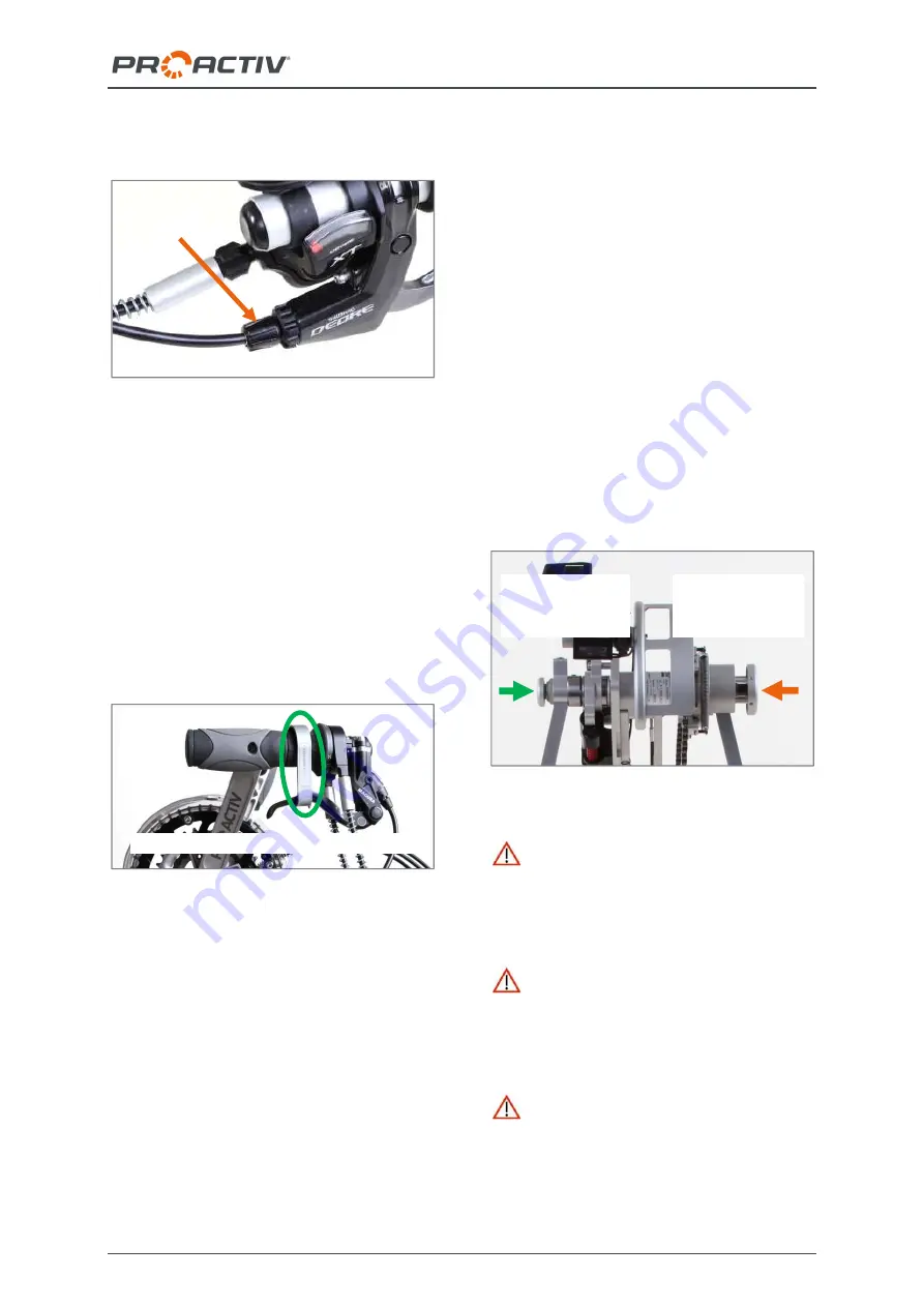
brake lever must always be checked for tight-
ness.
Figure 23: Setting screw on the brake lever
You can find further information in the brake
manufacturer's instructions.
17.4.2 Parking brake
An
aluminium bracket
is attached to the bot-
tom bracket support as a parking brake. With
it, one of the two brakes can be used as a
parking brake. For this purpose, the aluminium
bracket is clamped over the grip and the brake
lever while the brake lever is depressed.
Figure 24: Aluminium bracket as a parking brake
17.4.3 PRO ACTIV back-pedalling brake &
crank release function
The PRO ACTIV back-pedalling brake is a
closed hydraulic system consisting of a gener-
ator unit and a disc brake calliper. The system
has automatic wear compensation for the
brake pads.
The back-pedalling brake is delivered with a
crank release function that allows reverse driv-
ing and manoeuvring via the hand rims. As:
For functional reasons, the back-pedalling
brake always acts as soon as the product
moves backwards. Therefore, the user must
“unlock” the reverse movement first by operat-
ing the crank release function.
The braking function via the backward move-
ment (crank movement against the direction of
acceleration) is always guaranteed – with the
crank release function activated or deactivated.
The
braking force applied
is adjusted by the
strength of rotating the cranks backwards. The
braking force applied is adjusted by the
strength of rotating backwards.
The
crank release function
is operated by
pressing the side pressure plate. To activate
the crank release function, the left-hand pres-
sure plate must be operated (seen from the
direction of travel). To return to normal driving
operation with the back-pedalling brake, the
right-hand pressure plate must be operated.
Figure 25: Left- and right-hand pressure plates
Before every trip, test the brakes by mov-
ing the cranks with the normal operating force
in the direction opposite to acceleration. The
drive wheel must not be able to move when the
system is operated.
At regular intervals, check that all of the
connections, lines, bleed screws and the sur-
face of the transmitter unit do not leak and that
all the screw connections on the brake system
are tightened securely.
At regular intervals, check that the brake
pads and discs are free from grease, oil or
other contamination. In addition, check the
thickness of the brake disc. The minimum
thickness is printed on the brake disc. In addi-
Aluminium bracket as a parking brake
Setting screw
on the brake
lever
Deactivating the
crank
release function
Activating the
crank
release function


