NJ1 el. & FREAK el. compact bike usage instructions
28
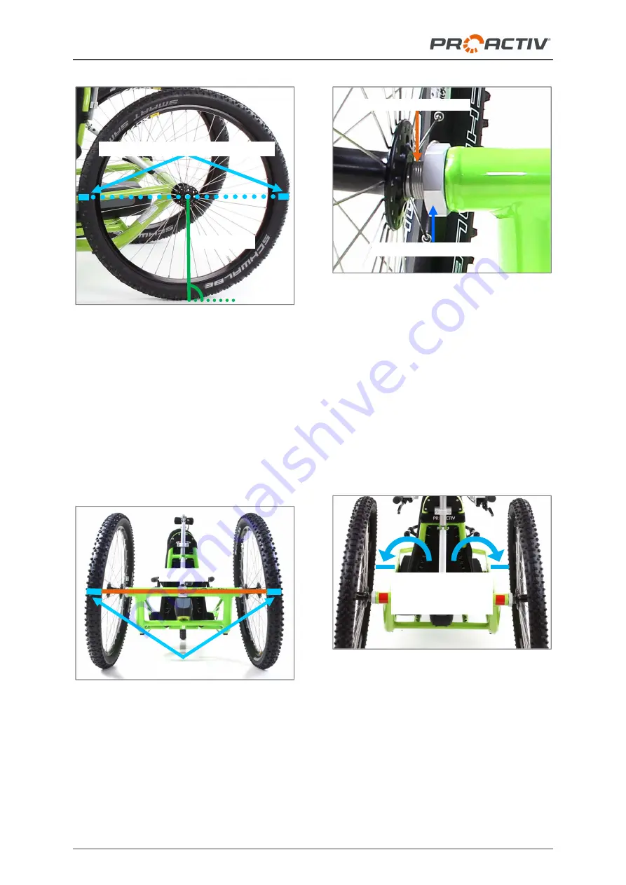
Figure 50: Drawing the axle height on the front and
back of both tyres of the running wheels
Afterwards measure the distance between the
running wheels front and back at the height of
the axles along the markers. Ideally, the dis-
tance between both running wheels should be
the same size at the front and back. In general,
it can be said that the distance between the
running wheels at the front and back may not
be larger 5 mm. If this is not the case, the
wheel tracking needs to be corrected.
Figure 51: Distance between the markers on the
tyres (at axle height), back
To
adjust the track
proceed as follows:
1. Loosen the aluminium locking nuts on both
sides (AF 41 mm).
Figure 52: Drive wheel bushing and aluminium lock-
ing nut (rear view)
2. Correctly adjust the track by turning the
drive wheel bushing (AF 24 mm). Here it
can be said that: If you turn the drive wheel
bushings in the direction of travel, the track
at the front will become narrower. The ex-
act opposite occurs if you turn it opposite
to the direction of travel; the track becomes
wider.
3. Make sure that the distance at the front to
the frame on the right and left is the same.
Figure 53: Distance at the front to the frame
•
Axle height
Drawing the axle height onto tyres
Distance
Markings
Aluminium locking nuts
Distance at front to
frame the same
size on both sides
Drive wheel bushing


