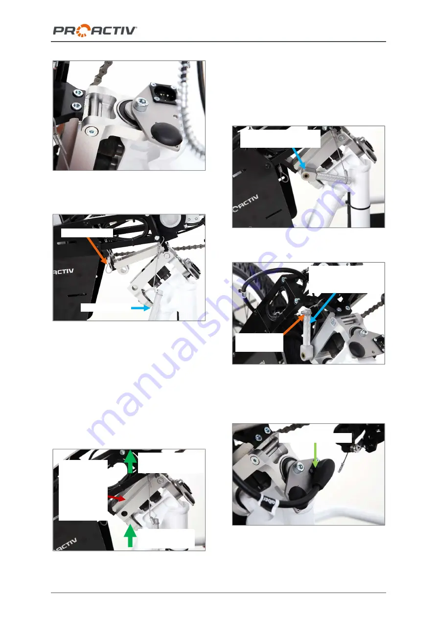
NJ1 el. & FREAK el. compact bike usage instructions
31
Figure 61: Insertion maul of the drive unit slips un-
der the insertion shaft on the chassis
Figure 62: Insertion maul of the drive unit hung into
the insertion shaft on the chassis, eccentric pin not
inserted yet
Finally, the chassis is raised at the front or the
drive unit is raised on the bottom bracket hous-
ing that the adapter plates of the drive unit and
chassis can completely rest on top of each
another. In doing so, make sure that the inser-
tion maul and the insertion shaft stay in posi-
tion.
Figure 63: Adapter plates of the drive unit and chas-
sis resting on top on one-another
Now the eccentric pin must be inserted on the
left side in the direction of travel, and the lever
of the eccentric pin must be turned upwards
approx. 90° counter-clockwise. Finally, the
securing cord is hung onto the lever of the
eccentric pin.
Figure 64: Eccentric pin inserted
Figure 65: Drive unit adapted completely
Finally, insert the magnetic connector into the
socket of the socket holder.
Figure 66: Magnetic connector inserted
Securing cord
hung on
Lever of the eccentric
pin closed (turned
upwards)
Eccentric pin inserted in
the adapter plate
Eccentric pin
Securing cord
Raise the pedal
bearing housing
Lift the chassis
at the front
Adapter
plates rest-
ing com-
pletely on
top on one-
another
Magnetic connector


