Operating instructions SPEEDY F1
27
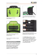
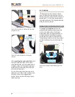
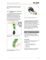
that the clamp lever does not protrude
sidewards over the anti-tipping support tube.
Figure 62: Pull the clamp lever out vertically to the
rotary axle
With the anti-tipping support version "Central
anti-tipping support with oversized tube, length
adjustable (Tennis)" different parts run inside
each other.
Contamination
, such as sand,
may prevent these anti-tipping supports from
being easily height adjustable.
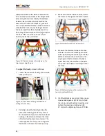
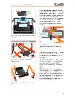
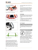
Figure 63: Anti-tipping supports with parts running
inside each other; description of clamp lever and M6
grub screw (sectional view)
In this case, the anti-tipping support must be
cleaned. To do this, proceed as follows:
1.
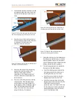
Remove the retaining ring on the end of
the anti-tipping support tube by loosening
the four M4 fixing screw (AF 2.5 mm).
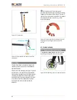
Figure 64: Retaining ring with M4 fixing screws
2.
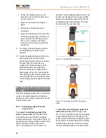
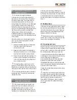
Remove the clamp lever by turning the
clamp lever anti-clockwise and slightly
loosen the M6 grub screw (AF 2 mm).
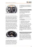
Figure 65: Clamp lever and M6 grub screw
Figure 66: Clamp lever removed and M6 grub screw
slightly loosened (sectional view)
Retaining ring
with M4 fixing
screws
M6 grub screw
Clamp lever
M6 grub screw
slightly loosened
Clamp lever
removed
M6 grub screw
Clamp lever
Pull the
clamp lever
out vertically
to the rotary
axle


