Operating instructions SPEEDY F1
28
3.
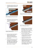
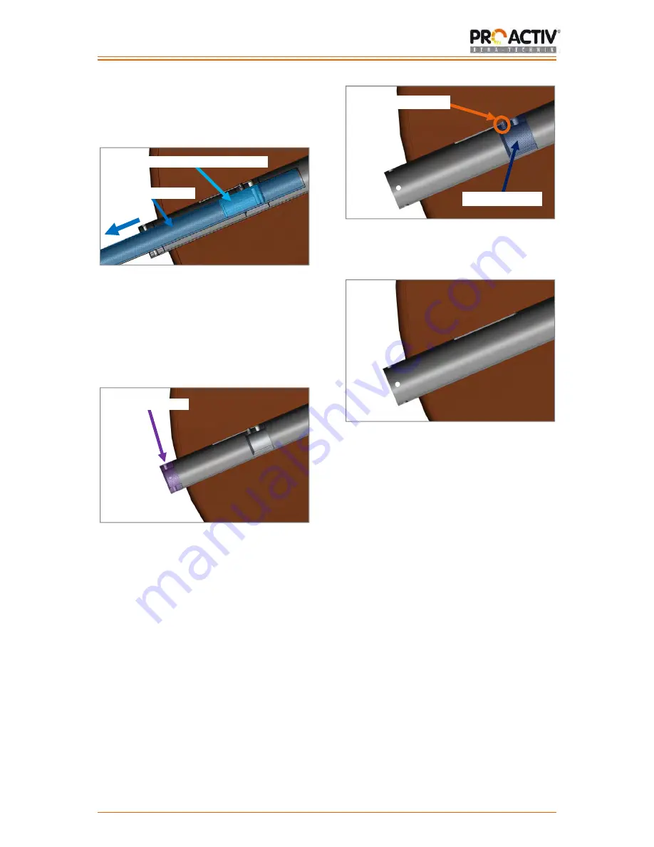
Pull the telescopic tube carefully out of the
anti-tipping support tube and ensure that
the inlet on the telescopic tube does not
move.
Figure 67: Pull out the telescopic tube with the inlet
from the anti-tipping support tube (sectional view)
4.
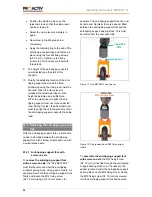
Now the screw-in inlet can be pulled out
of the anti-tipping support tube, if this has
not already come loose when the
telescopic tube was removed.
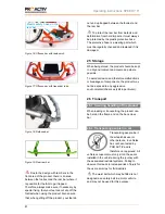
Figure 68: Telescopic tube pulled out; description of
the screw-in inlet (sectional view)
5.
Now clean the inside of the anti-tipping
support tube and the outside of the
telescopic tube (please note the
instructions in the "Cleaning and care"
chapter) until all the contamination has
been removed.
6.
Now remove the M6 grub screw and the
clamping piece. If the clamping piece
cannot easily be removed, loosen it by
gently tapping on the anti-tipping support
tube. If the clamping piece still is held
firmly in the tube, it can be pulled out
using an Allen key, for example.
Figure 69: Screw-in inlet removed; description of
clamping piece and threaded pin (sectional view)
Figure 70: All parts of the anti-tipping support
removed for cleaning (sectional view)
7.
Finally the retaining ring, the threaded pin,
the clamp lever and the screw-in inlet are
cleaned (please observe the instructions
in the "Cleaning and care" chapter) and all
sliding surfaces should be greased.
8.
The anti-tipping support is re-installed in
the reverse order after cleaning:
Insert the clamping piece back into the
anti-tipping support tube and screw in
the M6 grub screw by 1 to 2 turns.
Insert the screw-in inlet into the anti-
tipping support tube from the front.
Insert the telescopic tube into the anti-
tipping support tube and ensure that the
inlet found in there is correctly
positioned. Here, the thread on the inlet
for the clamp lever must be positioned
directly behind the hole for the clamp
lever in the telescopic tube.
Screw-in inlet
M6 grub screw
Inlet on the telescopic tube
Telescopic tube
Clamping piece


