Usage instructions SPEEDY F4 & F2
22
20.2.3 Adjusting the clothing guard posi-
tion
The following instructions are intended
for and may only be carried out by a rehabilita-
tion specialist dealer or PRO ACTIV
To
adjust
the clothing guard's position to the
drive wheel, the hole pattern in the front area
of the clothing guard can be used. To do this,
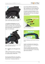
loosen the front M5 fixing screw (AF 3 mm)
with washer on both sides. Position the cloth-
ing guard as desired and insert the M5 fixing
screw with washer in the corresponding hole of
the hole pattern and into the clothing guard
bracket. Tighten up the M5 fixing screw (AF
3 mm) to 6 Nm.
Figure 37: Hole pattern to adjust the clothing guard
position (shown without drive wheel)
20.3 Clothing guard removable via lock
function
20.3.1 Overview of terms
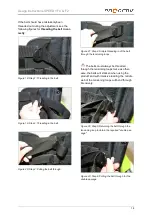
Figure 38: Back jointed shaft
Figure 39: Clothing guard removed from the product
Figure 40: Clothing guard fitted to the product
(product equipped with integrated brake or with
side-pull brake without brake retaining rail, shown
without drive wheel)
Figure 41: Clothing guard fitted to the product
(product equipped with knee-lever brake with brake
retaining rail, shown without drive wheel)
Side panel guide
Back jointed shaft
Back jointed shaft
Mounting bar
Recess for
"side panel guide"
Mount for
the "locking
pins"
Back jointed shaft
Side panel guide
Hole pattern to
adjust the clothing
guard position
Recess for "back
jointed shaft"


