Usage instructions SPEEDY F4 & F2
26
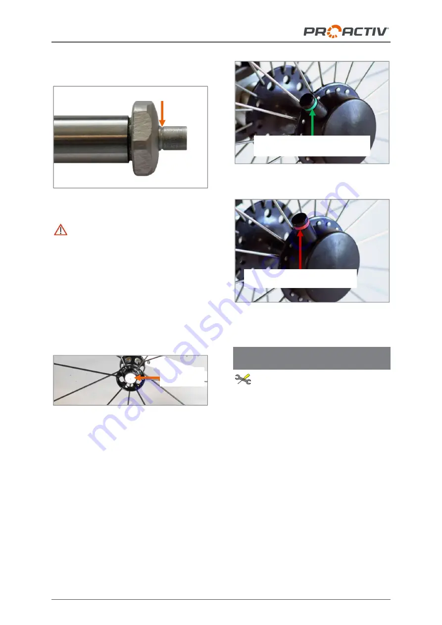
wise the wheels are not properly secured. You
will know this if you can see the index groove.
Figure 55: Quick release axle with index groove
Before using the product, check if the
wheels are secured and that the quick release
axles are locked.
The quick-release axle is equipped with the
small standard locking knobs (see previous
figure) as standard. The
quick-release axle
with operation support and large push but-
ton
can be equipped as an option. The se-
quence for removing and attaching the drive
wheels is identical with this option.
Figure 56: Quick-release axle with operation sup-
port, large push button
Recommended equipment:
For quadriplegics or people with limited finger
function, a
Tetra Clip
is available to operate
the quick-release axle lock. The Tetra Clip is a
plastic housing that is screwed onto the outer
side of the drive wheel hub and operated by
means of a push-through pin. The pin has a
red marking on one side (quick release axle
opened) and a green marking on the other side
(quick release axle locked). The pin can be
pushed using the ball of your hand in the direc-
tion of the middle of the drive wheel and there-
by the quick release axle opened or closed.
Figure 57: Tetra Clip with locked quick release axle
Figure 58: Tetra Clip with opened quick release
axle, drive wheel can be removed
21.2 Checking and adjusting the wheel
tracking of the drive wheel
The following instructions are intended
for and may only be carried out by a rehabilita-
tion specialist dealer or PRO ACTIV
Well adjusted wheel tracking significantly im-
proves the easy running characteristics of the
product. To
check
the tracking, proceed as
follows:
Position the product on a level surface and
secure the product against rolling away.
Measure the axle heights (from the ground to
the drive wheel axle) and write this dimension
onto both tyres at front and back.
Index groove
Red marking = drive wheel can
be removed
Green marking = drive wheel is
locked in place on the product
Large push
button


