Usage instructions SPEEDY F4 & F2
42
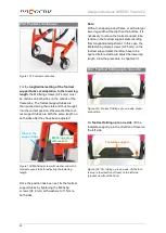
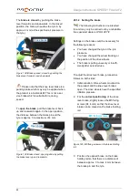
After "folding up to the back" each time, make
sure that the footrest has engaged correctly
again. This is visible when the locking pin lever
rests against the footbar joints (Fig. 112).
To
adjust the length of the footrest support
tubes
or adapt the lower leg length
, the M6
fixing screws (AF 4 mm) on the front sides of
the frame tubes must be released on both
sides. Fix the footrest support tubes to the
inlets using the M6 fixing screws (AF 4 mm)
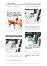
that have 3 holes that serve the setting of the
lower leg length. Only an extension of the low-
er leg length is possible as the footrest support
tube is always fixed in the top hole of the inlet.
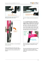
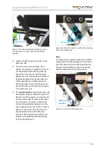
Figure 113: M6 fixing screw with washer to adjust
the lower leg length
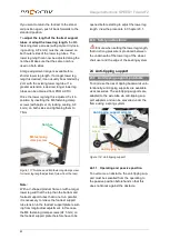
Figure 114: Inlet with 3 holes (view without footrest
support tube)
Once the M6 fixing screws (AF 4 mm) have
been loosened on both sides, move the foot-
rest support tubes so that the holes on both
sides of the footrest support tubes are posi-
tioned accurately over the holes of the under-
neath positioned inlet. Take care that the same
holes are used on both sides.
Once the position has been set, fix the footrest
support tubes by tightening the M6 fixing
screws (AF 4 mm) with washers to 11 Nm on
both sides.
23.5 Footrest folds up to the rear with
spring locking mechanism
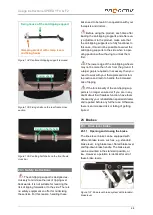
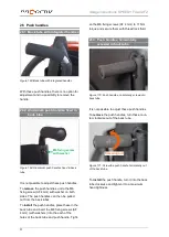
Figure 115: Footrest, folding up to the rear, with
spring latching mechanism, in standard position
To
fold the footrest up to the rear
, the foot-
plate must be pushed gently backwards until
the footrest is released from the lock. Now the
footrest can be folded up completely to the
rear.
Figure 116: Footrest, folding up to the rear, with
spring latching mechanism, folded up to the rear
M6 fixing screw
with washer
Support
tube


