Usage instructions SPEEDY F4 & F2
52
25.2.2 Setting the brake
The following instructions are intended
for and may only be carried out by a rehabilita-
tion specialist dealer or PRO ACTIV
Settings on the brake could be necessary for
the following reasons:
You have changed the tyre or the tyre
pressure.
You have changed the wheel tracking or
the position of the drive wheels.
The brake is pulling unevenly or insuffi-
ciently after extended use.
To adjust the knee lever brake with pull cable
operation, proceed as follows on both sides:
1. Initial situation: Drive wheels mounted on
the product and the knee lever brakes
open. The drive wheels have the specified
inflation pressure.
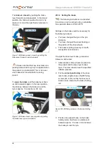
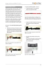
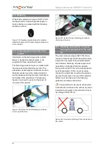
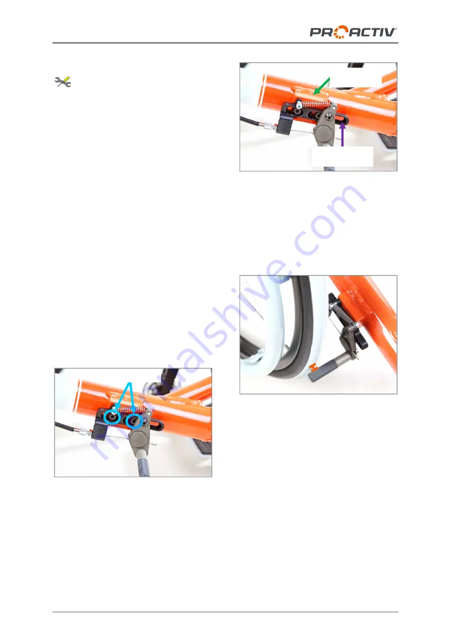
2. Slightly loosen the M5 fixing screws (AF
4 mm) which are used to attach the brake
to the brake mounting bar on the brake
mount.
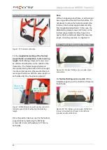
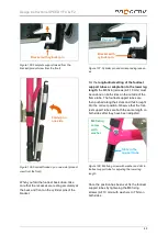
Figure 149: M5 fixing screws
Figure 150: Brake mount and brake mounting bar
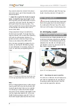
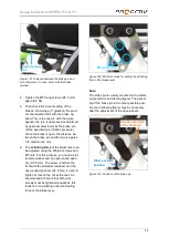
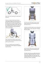
3. Position the open brake so that there is
approx. 3 mm clearance between the
brake pin and tyre up to a maximum of
4 mm. You can use the adjustment range
provided by the slots on the brake mount-
ing bar.
Figure 151: Distance between brake pin and tyre of
approx. 3 mm to maximum 4 mm, with opened
brake
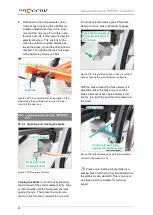
4. Tighten the M5 fixing screws (AF 4 mm)
again to 4
Nm.
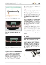
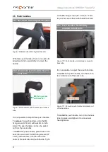
5. Then check the correct setting of the
brakes: On a slope (7° gradient) the prod-
uct should stand firm with the brake ap-
plied. This will happen if, with the brake
applied, the tyre is depressed or deformed
by approximately 4 mm by the brake pin
(at prescribed air pressure in the tyres).
When the brake is open, the distance be-
tween the brake pin and the tyre is approx.
3 to maximum 4 mm.
Brake mounting
bar with slots
Welded on
brake mount
M5 fixing screws


