TRAVELER 4all Ergo & 4you Ergo usage instructions
52
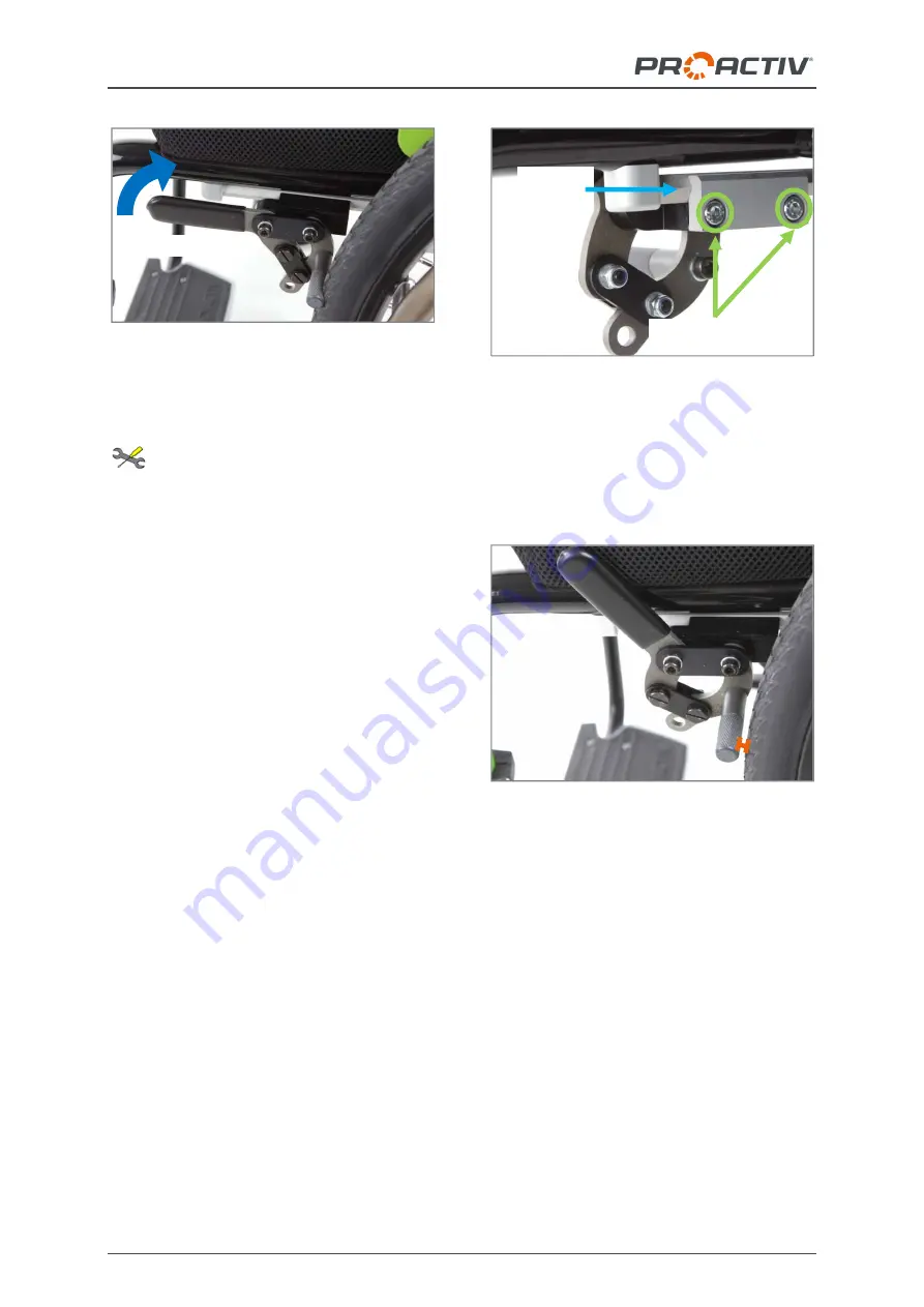
Figure 145: Brake closed; to open, pull the brake
lever up and rearwards
26.1.2 Setting the brake
The following instructions are intended
for and may only be carried out by a rehabilita-
tion specialist dealer or PRO ACTIV
Settings on the brake could be necessary for
the following reasons:
You have changed the tyre or the tyre
pressure.
You have changed the wheel tracking or
the position of the drive wheels.
The brake is pulling unevenly or insuffi-
ciently after extended use.
To adjust the knee lever brake, proceed as
follows on both sides:
1. Initial situation: Drive wheels mounted on
the product and the knee lever brakes
open. The drive wheels have the specified
inflation pressure.
2. For the
correct positioning
of the knee
lever brake, slightly loosen the M5 clamp
screws (AF 4 mm) so that the knee lever
brake can be moved on the hexagon rail.
Figure 146: M5 clamp screws on the hexagon rail
(view from the inner side of the product)
3. Position the opened brake on the hexagon
rail so that there is a distance of approx. 3
to max. 4 mm between the brake pin and
the tyre.
Figure 147: Distance between brake pin and tyre of
approx. 3 mm to maximum 4 mm, with opened
brake
4. Tighten the M5 clamp screws (AF 4 mm)
to 4
Nm again.
5. Then check the correct setting of the
brakes: On a slope (7° gradient) the prod-
uct should stand firm with the brake ap-
plied. This is the case if, with the brake
applied, the tyre is depressed or deformed
by approximately 4
mm by the brake pin
(at the specified tyre inflation pressure).
When the brake is open, the distance be-
tween the brake pin and the tyre is approx.
3 to maximum 4 mm.
6. The
actuating force
of the brake lever can
be adjusted using the M5 joint screws and
M5 clamp screws
Hexagon
rail
Open brake


