4
3.1 OPERATION INSTRUCTION
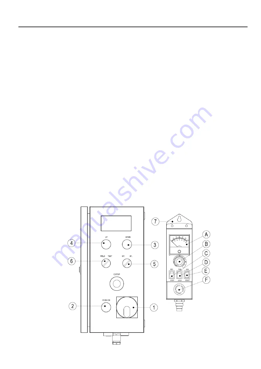
1. Rotary’s power switch
:
System’s control power switch .
2. “Start” switch (Power)
:
Turn ON the main power switch, press the control power switch ( power light ) to
start operation.
3. Tilt direction switch (Down)
:
Press button to move down direction; release to stop.
4. Tilt direction switch (Up)
:
Press button to move up direction; release to stop.
5. HP / RF switch (H.P / R.F)
:
A. H.P
:
the turning speed of rotation table is only controlled by hand pendant
,
foot switch has rotation /
stop function
。
B. R.F
:
the maximum speed of rotation table is controlled by hand pendant speed knob
,
the speed of
rotation table can be adjusted accordingly using foot variable speed control
。
6. Test / Weld switch (Test / Weld)
:
Weld
:
The welding output of JN1 is activated when pressing
“Run”
button of remote control device.
Test
:
The welding output of JN1 is always off
。
7. Remote control device
:
A. Speed meter
:
Shows the speed data (Hz.)
B. Speed knob
:
To increase speed, turn clockwise.
To decrease speed, turn counter clockwise.
C. Forward / Reverse
:
Indicates forward and reverse direction of the table.
Caution
:
[ While turning, please avoid changing direction. ]
D. Run / Stop
:
Set the
“Forward / Reverse”
direction followed by pressing the
“Run”
button to turn the
table continuously. Press
“Stop”
button to stop the turning.
E. Jog / Reset
:
While the machine is not in motion, you can adjust to desired position max speed by
pressing
“Jog”
function. When the inverter driver displays an error message, press
“Reset”
to clear the error and reset the system.
F. E-stop button
:
Press the emergency stop button to terminate the driver circuit.
Summary of Contents for PT-1000
Page 2: ......
Page 11: ...5 3 2 SEQUENCE DIAGRAM ...
Page 15: ...9 5 1 PARTS LIST MACHANISM PT 1000 ...
Page 17: ...11 5 2 PARTS LIST MACHANISM PT 2000 ...
Page 21: ...15 5 4 PARTS LIST CONTROL BOX ...
Page 22: ...16 6 1 CONTROL SYSTEM BOX ...
Page 23: ...17 6 2 MAIN CIRCUIT ...
Page 24: ...18 6 3 PENDANR CONTROL CIRCUIT ...
Page 32: ...26 CIRCUIT DIAGRAM ...


