7
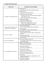
4.1 TROUBLE SHOOTING GUIDE
SYMP TOM
POSSIB LE C AU S E/ REME DY
6. The tilt cannot move or over tilt
A. Tilt direction switch breaks down.
Check / replace a new switch.
B. Failed control PC board.
Please refer to symptom No. 2.
C. Inverter breaks down, no output.
Please refer to symptom Nos. 3 & 4.
D. Limit switch breaks down.
(a) Inspect if limit switch contactor is in normal condition,
replace when necessary.
(b) Make sure the dog is in correct position, adjust when
needed.
E. Failed motor.
Check if there is input power voltage AC220V refer to
possible cause No.6.F.
F. The reducer is damaged.
Replace a new reducer.
7. Remote switch has no action or
speed control knob disable
A. Snap switch damaged.
Check / replace the snap switch contactor if necessary.
B. Potentiometer damaged.
Measure the potentiometer resistance (5KΩ), replace a new
one if needed.
C. Indicator not working.
Change the indicator.
8. Foot remote-speed control disable
A. Foot remote control’s limit switch damaged.
(a) Check if the limit switch contactor is in normal condition,
replace when necessary.
(b) Make sure the dog is in correct position, adjust when
needed.
B. Potentiometer damaged.
Measure the potentiometer resistance (5KΩ), replace a new
one if needed.
Summary of Contents for PT-1000
Page 2: ......
Page 11: ...5 3 2 SEQUENCE DIAGRAM ...
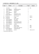
Page 15: ...9 5 1 PARTS LIST MACHANISM PT 1000 ...
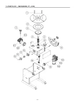
Page 17: ...11 5 2 PARTS LIST MACHANISM PT 2000 ...
Page 21: ...15 5 4 PARTS LIST CONTROL BOX ...
Page 22: ...16 6 1 CONTROL SYSTEM BOX ...
Page 23: ...17 6 2 MAIN CIRCUIT ...
Page 24: ...18 6 3 PENDANR CONTROL CIRCUIT ...
Page 32: ...26 CIRCUIT DIAGRAM ...


