24
Appendix A
:
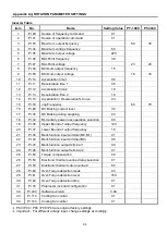
ROTATION PARAMETER SETTINGS
Inverter Table
Item
No.
Name
Setting Value
PT-1000
PT-2000
1
Pr.00
Source of frequency command
01
2
Pr.01
Source of operation command
01
3
Pr.03
Maximum output frequency
60
79
4
Pr.04
Maximum voltage frequency
60
5
Pr.05
Maximum output voltage
220
6
Pr.06
Mid-Point frequency
3.0
7
Pr.07
Mid-Point voltage
23
23
8
Pr.08
Minimum output frequency
1.5
9
Pr.09
Minimum output voltage
18
18
10
Pr.10
Acceleration time 1
0.5
11
Pr.11
Deceleration time 1
0.5
12
Pr.12
Acceleration time 2
1.0
13
Pr.13
Deceleration time 2
1.0
14
Pr.14
Acceleration / Deceleration S-Curve
03
15
Pr.16
Jog Frequency
60
79
16
Pr.28
DC Braking current level
30
17
Pr.30
DC Braking during stopping
0.3
18
Pr.32
Momentary power loss operation selection
00
19
Pr.36
Upper Bound of output frequency
120
20
Pr.37
Lower Bound of output frequency
1.5
21
Pr.38
Multi-function input terminal (M0,M1)
01
22
Pr.40
Multi-function input terminal (M3)
09
23
Pr.45
Multi-function output terminal 1
00
24
Pr.46
Multi-function output terminal 2
07
25
Pr.54
Torque compensation
00
26
Pr.58
Electronic thermal overload relay selection
01
27
Pr.59
Electronic thermal motor overload
60
28
Pr.60
Over-Torque detection mode
03
29
Pr.61
Over-Torque detection level
150
30
Pr.62
Over-Torque detection time
01
31
Pr.76
Parameter lock and configuration
01
32
Pr.100
Software version
3.04
33
Pr.114
Cooling fan control
01
34
Pr.144
Cooling fan control
01
*
P03 / P04 / P05 / P08 / P46 are original factory settings.
*
Important
:
For different voltage input, change settings accordingly.
Summary of Contents for PT-1000
Page 2: ......
Page 11: ...5 3 2 SEQUENCE DIAGRAM ...
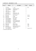
Page 15: ...9 5 1 PARTS LIST MACHANISM PT 1000 ...
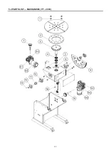
Page 17: ...11 5 2 PARTS LIST MACHANISM PT 2000 ...
Page 21: ...15 5 4 PARTS LIST CONTROL BOX ...
Page 22: ...16 6 1 CONTROL SYSTEM BOX ...
Page 23: ...17 6 2 MAIN CIRCUIT ...
Page 24: ...18 6 3 PENDANR CONTROL CIRCUIT ...
Page 32: ...26 CIRCUIT DIAGRAM ...


