25
Appendix B
:
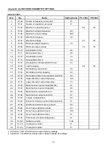
TILT PARAMETER SETTINGS
Inverter Tilt
Item
No.
Group 1
:
User parameter
Setting Value
PT-1000
PT-2000
1
1-00
Maximum output frequency (Fo. Max)
73
72
2
1-01
Maximum voltage frequency
60.0
3
1-02
Max. Output voltage (Vmax)
220
4
1-03
Mid-Point frequency (Fmid)
3.0
5
1-04
Mid-Point voltage (Vmid)
23
6
1-05
Minimum output frequency (F min)
1.5
7
1-06
Minimum output voltage (V min)
18
8
1-09
Acceleration time 1 (Taccel 1)
0.5
9
1-10
Deceleration time 1 (Tdecel 1)
0.5
10
1-11
Acceleration time 2 (Taccel 2)
1
11
1-12
Deceleration time 2 (Tdecel 2)
1
12
1-14
Jog Frequency
73
72
13
1-15
Auto Acceleration / Deceleration
0
14
1-16
S-Curve in Accel
3
15
1-17
S-Curve in Decel
3
Item
No.
Group 2
:
Operation method parameter
Setting Value
PT-1000
PT-2000
16
2-00
Source of frequency
0
17
2-01
Source of operation command
1
Item
No.
Group 4
:
Input function parameter
Setting Value
PT-1000
PT-2000
4-04
Multi-function Input terminal (M0,M1)
1
4-09
Line start lockout
1
Item
No.
Group 6
:
Protection parameter
Setting Value
PT-1000
PT-2000
6-06
Electronic thermal overload relay selection
1
6-07
Electronic thermal motor overload
60
*
P03 / P04 / P05 / P08 / P46 are original factory setting.
Summary of Contents for PT-1000
Page 2: ......
Page 11: ...5 3 2 SEQUENCE DIAGRAM ...
Page 15: ...9 5 1 PARTS LIST MACHANISM PT 1000 ...
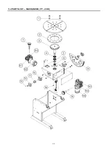
Page 17: ...11 5 2 PARTS LIST MACHANISM PT 2000 ...
Page 21: ...15 5 4 PARTS LIST CONTROL BOX ...
Page 22: ...16 6 1 CONTROL SYSTEM BOX ...
Page 23: ...17 6 2 MAIN CIRCUIT ...
Page 24: ...18 6 3 PENDANR CONTROL CIRCUIT ...
Page 32: ...26 CIRCUIT DIAGRAM ...


