background image


OWNER’S MANUAL 


Important

Read these instructions before installing, operating or servicing this product.


POSITIONING SYSTEM AND ACCESSORIES 

MODEL

PT

‒103 / PT‒203 

WELDING POSITIONERS 

(With CB-101/CB-102) 

Serial number

1808001 ~ and later 

Date : Aug. 21, 2018 

UNITED PROARC CORPORATION


No. 3 Gungye 10

th

 Road, Pingjen Industrial Park, 

Tel No

886 3 4696600 

Pingjen City, Taoyuan 324, Taiwan 

Fax No

886 3 4694499 

http

//www.proarc.com.tw 

E-Mail

customerservice@proarc.com.tw


RD-8457E 

Summary of Contents for PT-103

Page 1: ...SORIES MODEL PT 103 PT 203 WELDING POSITIONERS With CB 101 CB 102 Serial number 1808001 and later Date Aug 21 2018 UNITED PROARC CORPORATION No 3 Gungye 10 th Road Pingjen Industrial Park Tel No 886 3...

Page 2: ......

Page 3: ...ions ii Limited warranty iii 1 1 General information 1 1 2 Specification 2 2 1 Control panel 3 2 2 Operation 4 2 3 Installation 5 2 4 Timing diagram 6 3 1 Troubleshooting 7 4 1 Part List Mechanism PT...

Page 4: ...receive the equipment check it against the shipping documents Make sure it is complete and inspect the equipment for possible damage during shipping If there is any damage notify the carrier immediat...

Page 5: ...ral wire Interventions Before control and repair see the apparatus is switched off and insulated Connection with fixed installation cable is impossible It s on Stop and connection is impossible Some a...

Page 6: ...r apparatus clean and free from oil and grease Oxygen cylinders and apparatus should not be handled with oily hands or gloves Do not allow an oxygen stream to contact oily or greasy surfaces Do not us...

Page 7: ...option of the defected part only ProArc s option to repair or replacement of a defected part under this warranty shall be based on FOB Taiwan basis UNITED PROARC CORPORATION shall not be liable for an...

Page 8: ...through hole 22mm for gas purge application Faceplate with 3 straight slots for 3 jaws fixture PG 150 450L 500 mounting Control box selection CB 101 standard controller Speed adjuster Welding timer CB...

Page 9: ...tricity mm A 180 B 90 C 60 D 45 A 84 B 42 C 28 D 10 Table dimension E mm 320 Rotation speed rpm A 0 3 4 B 0 6 8 C 0 8 12 D 1 16 Spindle thru hole mm 22 Earthing Amp 200 100 300 40 Tilt range deg 0 120...

Page 10: ...eed selection switch SW3 5 Work Move mode selection switch SW2 6 Stop button STOP 7 Welding speed adjustment VR1 8 Welding timer adjustment VR2 9 Welding start delay timer adjustmen t VR3 For CB 102 1...

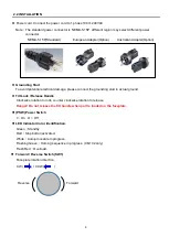
Page 11: ...ease connect the grounding stud to actual ground Tilt Lock Release Handle Clockwise rotation to lock counter clockwise rotation to release Danger Do not release the tilt handle when part is loaded on...

Page 12: ...e faceplate rotation Adjustable between 0 9 9 second Overlap Knob VR4 CB 102 only Active in WORK procedure Overlap is the time delay after faceplate has hit the home sensor before faceplate stops rota...

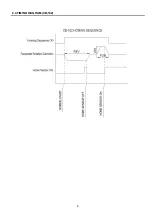
Page 13: ...6 2 4 TIMING DIAGRAM CB 102...

Page 14: ...nnector pin4 and pin5 The reading should be 0 short circuit Replace the footswitch when necessary D Inspect Control Board JP2 for loose connection E Inspect Control Board fuse F1 Welder start output n...

Page 15: ...and adjust the welding speed knob VR1 to desired speed Restart the homing sequence C Proximity switch too far Adjust the proximity switch so it can sense the homing block correctly D Proximity switch...

Page 16: ...2040010 20 Grounding brush w conducting seat 1 9 5114 12305105000 10 Grounding brush mounting plate 1 10 5114 12305104000 10 Reducer flange 1 11 5012 1150100 20 Reducer Shaft 1 12 5012 2320000 20 Tilt...

Page 17: ...10 4 1 PART LIST MECHANISM PT 103...

Page 18: ...ing brush w conducting seat 1 9 5114 12305105000 10 Grounding brush mounting plate 1 10 5114 12305104000 10 Reducer flange 1 11 5012 1150100 20 Shaft 1 12 5012 2360000 22 Tilting worm reducer 1 13 305...

Page 19: ...12 4 2 PART LIST MECHANISM PT 203...

Page 20: ...r supply 1 4 6651 1110 Printed circuit board 1 Motor speed control board 5 3545 5001 Grounding copper bar 1 6 3214 2009 Push button 1 7 3216 0006 Knob 2 VR1 VR2 3747 1001 8 Potentiometer w Connector 2...

Page 21: ...1 4 6651 1110 Printed circuit board 1 Motor speed control board 5 3545 5001 Grounding copper bar 1 6 3214 2009 Push button 1 7 3216 0006 Knob 3 VR1 VR3 VR4 3747 1001 8 Potentiometer w Connector 3 VR1...

Page 22: ...15 5 1 CIRCUIT DIGARM CB 101 CB 102...

Reviews: