4
2.2 INSTALLATION
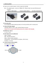
Power cord. Connect the power cord to 1 phase 100V~240VAC
Note
:
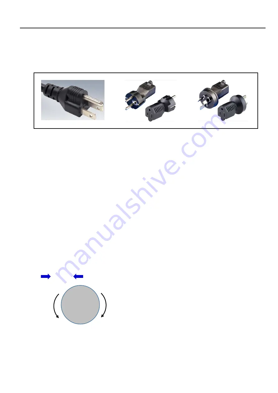
The standard power connector is NEMA-5-15P, different region may select different power
connector.
NEMA-5-15P(Standard) European Adapter(Option) Australian Adapter(Option)
Grounding Stud
To avoid potential electrical damage, please connect the grounding stud to actual ground.
Tilt Lock / Release Handle
Clockwise rotation to lock, counter clockwise rotation to release
Danger! Do not release the tilt handle when part is loaded on the faceplate.
(PSW) Power Switch
I = On
,
O = Off
LED Indicator Color Identification.
Green
:
Standby.
Red
:
Stop button activated.
White
:
Auto-procedure in progress.
Flashing Green
:
Homing sequence in progress. (CB-102 only)
Flash Red
:
Overload.
Forward / Reverse Switch (SW1)
Faceplate rotation direction.
CW ( ) / CCW ( )
Forward
Reverse
Summary of Contents for PT-103
Page 2: ......
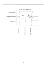
Page 13: ...6 2 4 TIMING DIAGRAM CB 102...
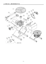
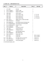
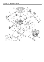
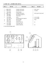
Page 17: ...10 4 1 PART LIST MECHANISM PT 103...

