background image


OWNER’S MANUAL 


Important

Read these instructions before installing, operating or servicing this product. 

POSITIONING SYSTEM AND ACCESSORIES 

MODEL

TR – 0104 

DIGITAL TURNING ROLL


Serial number

2101001 ~ and later 

Date : Jan. 06, 2021


UNITED PROARC CORPORATION 

No. 3 Gungye 10

th

 Road, Pingjen Ind. Park, 

Tel No

886 3 4696600 

Pingjen City, Taoyuan 324, Taiwan 

Fax No

886 3 4694499 

http

//www.proarc.com.tw 

E-Mail

customerservice@proarc.com.tw


  RD-8459AE 

Summary of Contents for TR-0104

Page 1: ...SYSTEM AND ACCESSORIES MODEL TR 0104 DIGITAL TURNING ROLL Serial number 2101001 and later Date Jan 06 2021 UNITED PROARC CORPORATION No 3 Gungye 10th Road Pingjen Ind Park Tel No 886 3 4696600 Pingjen...

Page 2: ......

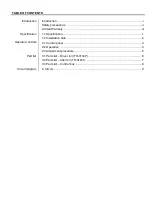
Page 3: ...ram Introduction i Safety precautions ii Limited Warranty iii 1 1 Specification 1 1 2 Installation hole 2 2 1 Control panel 3 2 2 Operation 4 2 3 Adjustment procedure 5 3 1 Parts list Driver roll TR 0...

Page 4: ...shipping documents Make sure it is complete and inspect the equipment for possible damage during shipping If there is any damage notify the carrier immediately to file a claim Furnish complete informa...

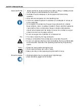
Page 5: ...ral wire Interventions Before control and repair see the apparatus is switched off and insulated Connection with fixed installation cable is impossible It s on Stop and connection is impossible Some a...

Page 6: ...r apparatus clean and free from oil and grease Oxygen cylinders and apparatus should not be handled with oily hands or gloves Do not allow an oxygen stream to contact oily or greasy surfaces Do not us...

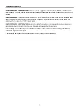
Page 7: ...option of the defected part only ProArc s option to repair or replacement of a defected part under this warranty shall be based on FOB Taiwan basis UNITED PROARC CORPORATION shall not be liable for an...

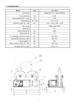
Page 8: ...1 000 Speed range mm min 80 1 600 Diameter range G G1 mm 20 500 400 800 Drive motor PMDC Motor 65W Roller type PU Roller diameter E mm 200 Roller width F mm 50 Overall length A Drive Idler mm 470 450...

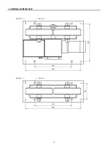
Page 9: ...2 1 2 INSTALLATION HOLE...

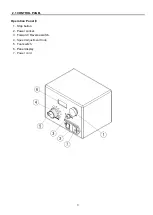
Page 10: ...3 2 1 CONTROL PANEL Operation Panel 1 Stop button 2 Power socket 3 Forward Reverse switch 4 Speed adjustment Knob 5 Foot switch 6 Panel display 7 Power cord...

Page 11: ...pause all motion and disable all control Rotate the Stop button clockwise to reset 5 Speed Adjustment Knob VR1 Rotate clockwise to increase speed counter clockwise to decrease speed 6 Foot switch F S...

Page 12: ...p 1 Step 2 Step3 Use 17mm wrench and adjust the nut in clockwise direction until the PU roller moves Press the rollers with approximate 20 30 kg pressure and check for any slip on the PU rollers Start...

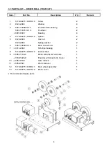
Page 13: ...8 02271103040 10 Spacer 4 5 0123 2000 Hex nut 2 0122 2000 Spring washer 2 6 5041 1020000 10 Main drive wheel 1 7 0311 2002 Fish Eye bearing 1 8 5118 02271104020 10 Internal Stud 1 9 0361 1104 9 Motor...

Page 14: ...03030 10 Screw 2 2 0121 2000 Washer 4 3 5041 1030000 10 Pu wheel with bearing 2 5041 1030100 10 Pu wheel 2 0301 0403 Deep groove ball bearing 4 4 5118 02271103040 10 Spacer 4 5 0123 2000 Nut 2 0122 20...

Page 15: ...3242 1118 Foot switch 1 Cable 3M 6 3445 2009 Power socket 1 7 3445 0001 AC Power cord 1 Option Standard 3456 0003 AC Power cord 1 Option European 3456 0004 AC Power cord 1 Option Australian 3456 0005...

Page 16: ...9 4 CIRCUIT DIAGRAM...

Reviews: