background image


OWNER’S MANUAL


Important

Read these instructions before installing, operating or servicing this product.


MODEL

TR 

 3504


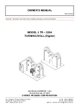
TURNING ROLL (Digital) 

Serial Number

200907003 ~ Later 

Revised Date: Sep. 18

th

, 2020 

UNITED PROARC CORPORATION


No. 3 Gungye 10

th

 Road, Pingjen Ind. Park, 

Tel No

886 3 4696600 

Pingjen City, Taoyuan 324, Taiwan 

Fax No

886 3 4694499 

http

//www.proarc.com.tw 

E-Mail

customerservice@proarc.com.tw 

RD-8447AE 

Summary of Contents for TR-3504

Page 1: ...t MODEL TR 3504 TURNING ROLL Digital Serial Number 200907003 Later Revised Date Sep 18th 2020 UNITED PROARC CORPORATION No 3 Gungye 10th Road Pingjen Ind Park Tel No 886 3 4696600 Pingjen City Taoyuan 324 Taiwan Fax No 886 3 4694499 http www proarc com tw E Mail customerservice proarc com tw RD 8447AE ...

Page 2: ......

Page 3: ... precautions ii Limited warranty iii 1 1 Features 1 1 2 Specification 2 1 3 Installation 3 2 1 Remote control instruction 4 3 1 Trouble shooting guide 6 4 1 1 Parts list Power roll TR 3504P 8 4 1 2 Parts list Idler roll TR 3504I 9 4 2 Parts list Control box 10 5 1 Control circuit 12 5 2 Control system box 15 Inverter settings 16 Wiring diagram 18 ...

Page 4: ...e equipment for possible damage during shipping If there is any damage notify the carrier immediately to file a claim Furnish complete information concerning damage claims or mistake s in shipment to United ProArc Corporation No 3 Gungye 10th Road Pingjen Ind Park Pingjen City Taoyuan 324 Taiwan Include the equipment identification number along with a description of the parts in question Move the ...

Page 5: ...th must never be cut by the protection device against electrical shocks Work Place Be very careful to avoid contact between metal part and phase conductor and the neutral of electric network Electrical messes of different electrical machine and apparatus are connected between themselves and with the terminal of earth neutral wire Interventions Before control and repair see the apparatus is switche...

Page 6: ... your health Ventilation must be adequate to remove gases and fumes during operation Keep all fumes and gases from the breathing area Use an air supplied respirator if ventilation is not adequate to remove all fumes and gases Oil or grease in the presence of oxygen may ignite and burn violently Keep cylinders valves couplings regulators hoses and other apparatus clean and free from oil and grease ...

Page 7: ...on to repair or replacement of a defected part under this warranty shall be based on FOB Taiwan basis The warranty period begins on the date of sale to the original purchase user of the equipment UNITED PROARC CORPORATION shall not be liable for any loss or consequential damage or express accruing directly or indirectly from the use of equipment covered by this warranty This warranty supersedes al...

Page 8: ...T T TH H HI I IS S S P P PA A AG G GE E E I I IS S S B B BL L LA A AN N NK K K ...

Page 9: ...work range from 9mm to 1200mm diameter without changing wheel center Forward Stop Reverse switch with potentiometer for step less speed adjustment Ideal where pipe works for welding PU rubber tires provide friction drive and uniformly smooth pipe rotation ...

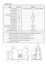
Page 10: ...00 Roller Width E mm 100 Roller Type PU Overall Width A Driver Idler mm 425 280 Overall Length B Drive Idler mm 780 700 Overall Height C mm 520 Net Weight Drive Idler kg 165 110 55 Installation location Altitude 1000M or below Free from corrosive gas and liquid Ambient temperature 0 40 non condensing and not frozen Ambient humidity Below 90 RH non condensing Storage temperature 20 60 non condensin...

Page 11: ...3 1 3 INSTALLATION Power Roll Idler Roll ...

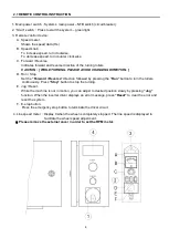
Page 12: ...n Stop Set the Forward Reverse direction followed by pressing the Run button to turn the rollers continuously Press Stop button to stop the turning E Jog Reset While the machine is not in motion you can adjust to desired position slowly by pressing Jog function When the inverter driver displays an error message press Reset to clear the error and reset the system F E stop button Press the emergency...

Page 13: ...5 2 1 REMOTE CONTROL INSTRUCTION ...

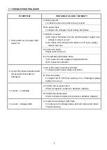
Page 14: ...ator light breaks down a To make sure the voltage of indicator DC24V b To inspect the indicator 2 Control PC board indicator LED lamp wasn t illuminated or damaged A AC or DC power input disconnected To inspect power input voltage and phase B Fuse burn down To inspect the F1 F2 fuse working or not If damaged please replace a new one 3 Inverter no display A Inverter has no power input Check if magn...

Page 15: ...trol PC board Please refer the item 2 C Inverter breaks down no output Please refer the item 3 4 D Failed motor Check change a new motor E The reducer is damaged Replace a new reducer 6 Remote switch has no action A Snap switch damaged To check the snap switch connector is normal or not And replace it B Indicator was no work To change the indicator ...

Page 16: ...oller 1 0301 0403 Bearing 2 2 5045 1560100 10 Friction wheel 2 3 5045 1560200 10 Friction shaft 2 4 0301 0403 Deep Groove ball bearing 4 5 0123 2000 Hex nut 4 0122 2000 Spring washer 4 6 5045 1540300 10 Screw 4 7 0353 0303 Worm reducers 1 8 0350 0045 Reducer motor 1 9 5045 1570000 22 Driving roller 1 10 0311 2001 Joint bearing 1 Recommended spare parts ...

Page 17: ... Item Part No Description Q ty Remark 1 5041 1030000 10 PU roller with bearing 6 Roll Bearing 5041 1030100 10 PU roller 1 0301 0403 Bearing 2 2 5045 1540300 10 Screw 4 3 0123 2000 Hex nut 4 0122 2000 Spring washer 4 Recommended spare parts ...

Page 18: ...ith AC220V 3221 3008 No Fuse breaker 1 With 4AC60V 8 6652 1221 PC Board 1 PCB 9 3021 2101 Inverter 1 INV With AC220V 3021 4101 Inverter 1 INV With AC460V 10 3311 0018 Transformer 1 With AC460V 11 3071 2201 Fan 1 With AC460V 12 3211 4105 Select switch 1 Options for VSFC 13 3122 4004 Socket female 10Pin 1 Options for VSFC 14 3122 7002 Socket female 17 Pin 1 JN4 15 3122 4003 Female male connector 7 P...

Page 19: ...11 T T TH H HI I IS S S P P PA A AG G GE E E I I IS S S B B BL L LA A AN N NK K K ...

Page 20: ...12 5 1 CONTROL CIRCUIT 1ψ220V ...

Page 21: ...13 5 1 CONTROL CIRCUIT 3ψ380V 415V 460V ...

Page 22: ...14 5 1 CONTROL CIRCUIT REMOTE CONTROL ...

Page 23: ...15 5 2 CONTROL SYSTEM BOX 1ψ220V 3ψ380V 460V ...

Page 24: ...alue 01 00 Maximum operation frequency 0 00 599 00Hz 60 01 01 Output frequency of motor 1 Base frequency motor s rated voltage Frequency of motor setting 60 01 02 Output voltage of motor 1 Base voltage motor s rated voltage Voltage of motor setting 220 380 01 03 Mid point frequency 1 of motor 1 0 00 599 00Hz 3 01 04 Mid point voltage 1 of motor 1 230V models 0 0V 240 0V 460V models 0 0V 480 0V 23 ...

Page 25: ...mber of poles for induction motor 1 Depending on the model number of poles 4 05 05 No load current for induction motor 1 A Depending on the model power 1 12 06 Protection Parameters 1 Pr No Parameters Function Explanation Setting Value 06 06 Over Torque detection selection motor 1 3 Continue operation after over torque decoction during run 3 06 07 Over Torque detection level motor 1 0 250 100 corr...

Page 26: ...18 APPENDIX B CIRCUIT AC220V 1 PHASE ...

Page 27: ...19 APPENDIX B CIRCUIT AC380 415V 460V 3 PHASE ...

Reviews: