4
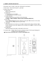
2.1 REMOTE CONTROL INSTRUCTION
1. Main power switch
:
System’s main power
‒
NFB switch (circuit breaker).
2. “Start” switch
:
Press to start the system – green light.
3. Remote control device
:
A. Speed meter.
Shows the speed data (Hz.)
B. Speed knob.
To increase speed, turn clockwise.
To decrease speed, turn counter clockwise.
C. Forward / Reverse
Indicates forward and reverse direction of the turning rollers.
CAUTION : [ WHILE TURNING, PLEASE AVOID CHANGING DIRECTION. ]
D. Run / Stop.
Set the
“Forward / Reverse”
direction followed by pressing the
“Run”
button to turn the rollers
continuously. Press
“Stop”
button to stop the turning.
E. Jog / Reset.
While the machine is not in motion, you can adjust to desired position slowly by pressing
“Jog”
function. When the inverter driver displays an error message, press
“Reset”
to clear the error and
reset the system.
F. E-stop button.
Press the emergency stop button to terminate the driver circuit.
4. Line speed meter
:
Display 0 when the wheel is completely stopped. The line speed is displayed to
facilitate the wheel speed adjustment.
﹡
Please remove the external cover in order to set the RPM meter.
Summary of Contents for TR-3504
Page 2: ......
Page 8: ...T T TH H HI I IS S S P P PA A AG G GE E E I I IS S S B B BL L LA A AN N NK K K ...
Page 11: ...3 1 3 INSTALLATION Power Roll Idler Roll ...
Page 13: ...5 2 1 REMOTE CONTROL INSTRUCTION ...
Page 19: ...11 T T TH H HI I IS S S P P PA A AG G GE E E I I IS S S B B BL L LA A AN N NK K K ...
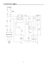
Page 20: ...12 5 1 CONTROL CIRCUIT 1ψ220V ...
Page 21: ...13 5 1 CONTROL CIRCUIT 3ψ380V 415V 460V ...
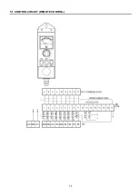
Page 22: ...14 5 1 CONTROL CIRCUIT REMOTE CONTROL ...
Page 23: ...15 5 2 CONTROL SYSTEM BOX 1ψ220V 3ψ380V 460V ...
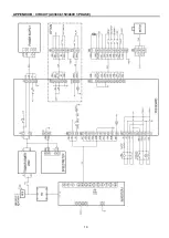
Page 26: ...18 APPENDIX B CIRCUIT AC220V 1 PHASE ...
Page 27: ...19 APPENDIX B CIRCUIT AC380 415V 460V 3 PHASE ...

