background image

10

WARNING

After 

ANY

 adjustments, repair or service and 

BEFORE

 use, ensure 

that all attaching hardware is tightened securely - otherwise injury or 

damage may result.

CAUTION

Ensure that there is adequate room to operate the ProBasics Mobile 

Recliner. There must be at least three feet clearance between the top of 

the recliner back and the surrounding objects, otherwise damage to the 

recliner and or surrounding property may occur.

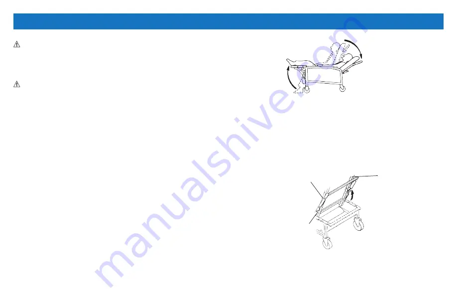
RECLINING THE CHAIR

USER RECLINE

NOTE:

 For this procedure, refer to

 FIGURE 4.1

.

NOTE:

 The chair cannot recline if the recline lock bar is engaged. An 

assistant must first swing recline lock bar up to the chair back and lock 

into position.

1.    While seated in the recliner, grip the armrests and simultaneously 

lean body weight back and push forward with your arms until a 

recline position reached.

NOTE:

 The footrest will lift automatically when the chair back reclines.

NOTE:

 The occupant should not be required to exert excessive force to 

change recline positions. If the recliner exhibits difficulty in reclining, an 

attendant should be called for assistance.

FIGURE 4.1   

RECLINING THE CHAIR - USER RECLINE

ASSISTED RECLINE

NOTE:

 For this procedure, refer to 

FIGURE 4.2

.

1.   Swing recline lock bar up to chair back and lock into position.

2.    Grasp the armrest with one hand and the push bar with the other 

hand.

3.    Push the back of the chair down slowly until a desired position is 

reached.

FIGURE 4.2   

RECLINING THE CHAIR - ASSISTED RECLINE 

NOTE:

 The caregiver can set recline lock bar at one of the three locking 

positions.

SECTION 4—OPERATION

Back

Assembly

Position

Lock Lever

Storage

Position

Summary of Contents for PB6074

Page 1: ...ding ProBasics products parts and services please visit www compasshealthbrands com DEALER This manual MUST be given to the user of the product USER BEFORE using this product read this manual in its e...

Page 2: ...lth Brands recommends that Mobile Recliner users NOT be transported in vehicles of any kind while in mobile recliners Currently the US Department of Transportation DOT has not approved any tie down sy...

Page 3: ...Lock Lever 14 Installing Position Lock Lever 14 Replacing Casters 14 Replacing Caster Assembly 14 TABLE OF CONTENTS Replacing Caster Wheels 14 Replacing Plunger Release Knob 15 Removing Installing the...

Page 4: ...ractices which could result in personal injury or property damage Refer to the following table for definitions of the signal words SIGNAL WORD MEANING DANGER Danger indicates an imminently hazardous s...

Page 5: ...1 OVERALL TRAY LENGTH AND WIDTH 25 x 15 inches WEIGHT LIMITATION 250 lbs PRODUCT WEIGHT 91 lbs SHIPPING WEIGHT 105 lbs MODEL NO PB6074WD OVERALL HEIGHT 47 inches OVERALL WIDTH 32 inches OVERALL DEPTH...

Page 6: ...the recliner NEVER stand on the footplates When getting in or out of the wheelchair make sure that the footplates are in the upward position or swing the footrests towards the outside of the wheelchai...

Page 7: ...250 lbs 113 6 kg The weight limitation for model PB6074WD Wide Recliner is 400 lbs 181 44 kg The tray for model PB6074 has a weight limitation of 40 lbs 18 2 kg RECLINE OPTION OPERATED BY AN ATTENDAN...

Page 8: ...pun Caster should come to a gradual stop Loosen tighten caster locknut if wheel wobbles noticeably or binds to a stop Ensure that the caster assembly is free from debris Inspect for any loose hardware...

Page 9: ...rame with cushion 3 Lift the chair back in an upright position behind the rear seat cross brace 4 Slide the back tubes into the open tube ends of the rear seat cross brace 5 Lift the plastic skirt mou...

Page 10: ...he armrests and simultaneously lean body weight back and push forward with your arms until a recline position reached NOTE The footrest will lift automatically when the chair back reclines NOTE The oc...

Page 11: ...on the plunger release knobs on both arms and twist them turn to lock them in the open position 2 Pull the tray up and clear from the hangers located on the side of the recliner 3 Align the alignment...

Page 12: ...headrest bracket to the back cushion with four short hex screws 4 Securely tighten Repeat for remaining headrest bracket FIGURE 5 1 Replacing the Back Cushion REPLACING THE FOOTREST CUSHION WARNING N...

Page 13: ...dge down 7 Align holes of new recline mechanism guard with holes on side frame 8 Secure new recline mechanism guard to side frame with bolts A B C and D Securely tighten 9 Install the side panel Refer...

Page 14: ...gn hole in caster insert with hole in recliner frame and install new caster assembly 4 Reinsert and tighten the hex head screw and nut 5 Return the recliner to its upright position WARNING Periodic in...

Page 15: ...plunger pin 7 Snap the retaining ring into groove of the plunger pin 8 Replace the glide into the end of the frame FIGURE 5 6 Replacing Plunger Release Knob REMOVING INSTALLING THE SIDE PANEL NOTE For...

Page 16: ...side frame FIGURE 5 7 Removing Installing the Side Panel REPLACING THE ARMREST CUSHION NOTE For this procedure refer to FIGURE 5 8 REMOVING ARMREST CUSHION 1 Remove four screws securing the armrest c...

Page 17: ...ou may also have other legal rights which vary from state to state Compass Health Brands warrants the products manufactured to be free from defects in materials and workmanship for a period of three y...

Page 18: ...O PROBLEMS ARISING FROM NORMAL WEAR OR FAILURE TO ADHERE TO THE INSTRUCTIONS IN THIS MANUAL THE FOREGOING WARRANTY IS EXCLUSIVE AND IN LIEU OF ALL OTHER EXPRESS WARRANTIES IMPLIED WARRANTIES IF ANY IN...

Page 19: ...Manufactured for Compass Health Brands Corp Middleburg Heights OH 44130 www compasshealthbrands com 800 376 7263 Made in China 42 PB6074_01 2018...

Reviews: