Description
15 / 21
4.
Description
This chapter provides general information about the machine. This chapter is intended for the
owner, the operator and the maintainer of the machine.
4.1.
General
This user manual includes an appendix with an exploded view drawing. This drawing includes a
parts list containing the name of each part.
4.2.
Construction of the machine
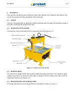
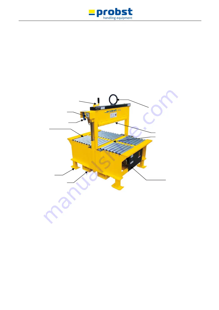
The machine consists primarily of the components shown in Figure 4.2-1.
Figure 4.2-1: Construction of the machine
4.3.
Electrical supply
The machine is equipped with the required male/female plug connection. The required supply
voltage is 230 VAC. A 3-conductor mains cable is required. For the location and construction of
the plug connection, see Figure 4.2-1
4.4.
Safety provisions and warning symbols
The safety provisions and warning symbols are handled in sections 3.1 and 3.2.
Lifting eye
Adjustment handle, upper blade
Plug connection, mains power
Support legs
Roller bed
Fork lift tubes
Upper blade
Lower blade
Housing hydraulic
unit
Push button, cutting
Summary of Contents for AL-90
Page 3: ......
Page 29: ......
Page 30: ...51200054 V1 GB Opreration Instructions Hydraulic block cutter Typ AL 90 NSH 40 ...


