background image

Operation


12 / 18


5450.0004 

V3 

GB 


Fig. 1 


Fig. 2 


5.1.1


Adjustment of the height-adjustable support 

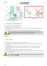
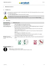
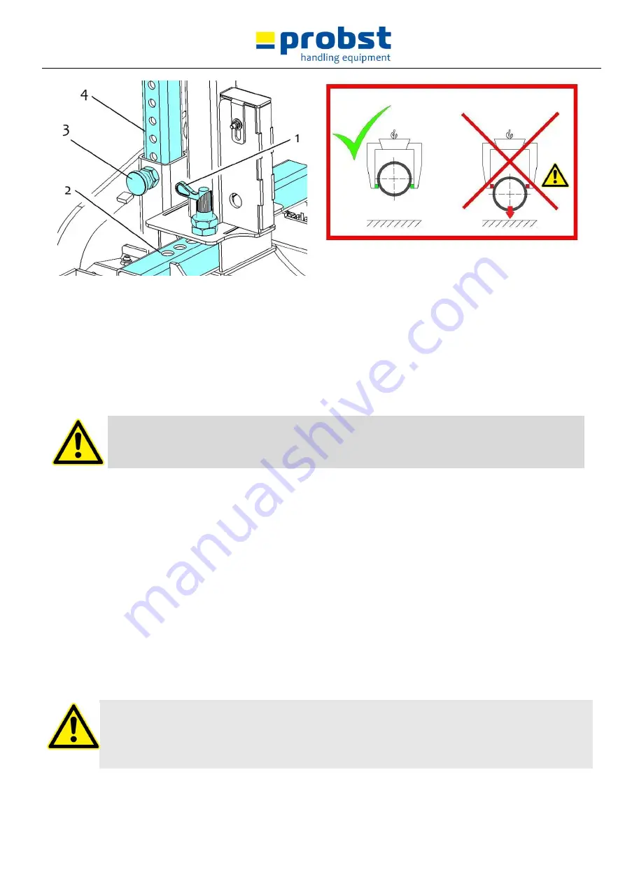
The height-adjustable support is adjusted as follows: 


Pull the cotter pin (3) upwards and turn it by 180°. 


Move the rectangular tube (4) until the correct immersion depth is set. Pull the cotter pin (3) upwards again and 
turn it by 180°.  


Push the rectangular tube (4) back and forth until the spring bolt (3) engages in the corresponding hole. 


The height-adjustable support must always be set so that the gripping jaws always grip the concrete 
pipe below the largest pipe diameter, otherwise there is a danger of slipping!!  

 Fig. 2


6


Operation 


6.1


Device operation 


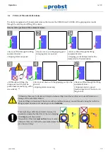
- Attach the device (RG-8/40) to the carrier/hoist using the suspension eye. 


- Adjust the opening width/gripping range and height-adjustable support according to the material to be gripped 
(concrete pipe). 


- Position the implement (RG-8/40) above the material to be gripped and lower it until the support rests on it. 


- As soon as the implement is completely lowered, the automatic changeover unlocks and closes during the 
subsequent lifting. 


- Transport the material to be gripped (concrete pipe) to the determination position. 


- Lower the implement (RG-8/40). The automatic change-over switches to locking when the load is relieved, whereby 
the device can be lifted again. 


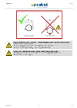
Goods to be gripped (concrete pipes) must always be gripped below the largest pipe diameter, otherwise 
there is a danger of slipping! 


Summary of Contents for RG-40

Page 1: ...5450 0004 V3 DE GB Bedienungsanleitung Operating Instructions RG 8 40 ...

Page 2: ...sanleitung in Landessprache falls die Übersetzung nicht durch den Händler Importeur organisiert werden kann Please note that the product may not be used put into operation without these operating instructions in the national language If you did not receive operating instructions in your national language with the delivery of the product please contact us In countries of the EU EFTA we will send th...

Page 3: ......

Page 4: ......

Page 5: ...5450 0004 V3 DE Betriebsanleitung Original Betriebsanleitung Rohrgreifer RG 8 40 ...

Page 6: ...mäßer Einsatz 8 3 2 Übersicht und Aufbau 10 3 3 Technische Daten 10 4 Installation 11 4 1 Mechanischer Anbau 11 4 1 1 Einhängeöse Einhängebolzen 11 4 1 2 Lasthaken und Anschlagmittel 11 4 1 3 Einstecktaschen optional 12 4 1 4 Drehköpfe optional 12 5 Einstellungen 13 5 1 Einstellung des Greifbereichs 13 5 1 1 Einstellung der höhenverstellbaren Auflage 13 6 Bedienung 14 6 1 Bedienung allgemein 14 6 ...

Page 7: ...enrichtlinie Folgende Normen und technische Spezifikationen wurden herangezogen DIN EN ISO 12100 Sicherheit von Maschinen Allgemeine Gestaltungsleitsätze Risikobeurteilung und Risikominderung ISO 12100 2010 DIN EN ISO 13857 Sicherheit von Maschinen Sicherheitsabstände gegen das Erreichen von Gefährdungsbereichen mit den oberen und unteren Gliedmaßen ISO 13857 2008 Dokumentationsbevollmächtigter Na...

Page 8: ...rd Öffnungsweite setzt sich aus dem Greifbereich und dem Einfahrmaß zusammen Greifbereich Einfahrmaß Öffnungsbereich Eintauchtiefe entspricht der maximalen Greifhöhe von Greifgütern bedingt durch die Höhe der Greifarme des Gerätes Gerät ist die Bezeichnung für das Greifgerät Produktmaß sind die Abmessungen des Greifgutes z B Länge Breite Höhe eines Produktes Eigengewicht ist das Leergewicht ohne G...

Page 9: ...r Größe Quetschgefahr der Hände 2904 0221 2904 0220 2904 0107 30 x 30 mm 50 x 50 mm 80 x 80 mm GEBOTSZEICHEN Symbol Bedeutung Bestell Nr Größe Jeder Bediener muss die Bedienungsanleitung für das Gerät mit den Sicherheitsvorschriften gelesen und verstanden haben 2904 0665 2904 0666 Ø 30 mm Ø 50 mm OPTIONAL Einstecktasche und Gabelstaplerzinken mittels Arretierungsschraube und Sicherungskette oder S...

Page 10: ...ssen angefrorenen oder verschmutzten Baustoffen Das Arbeiten mit dem Gerät bei Witterungsverhältnissen unter 3 C 37 5 F ist verboten Es besteht die Gefahr des Abrutschens der Greifgüter bedingt durch Nässe oder Vereisung 2 8 Funktions und Sichtprüfung 2 8 1 Allgemeines Das Gerät muss vor jedem Arbeitseinsatz auf Funktion und Zustand geprüft werden Wartung Schmierung und Störungsbeseitigung dürfen ...

Page 11: ...als außermittig aufnehmen stets im Lastschwerpunkt ansonsten Kippgefahr Das Gerät darf nicht geöffnet werden wenn der Öffnungsweg durch einen Widerstand blockiert ist Die Tragfähigkeit und Nennweiten des Gerätes dürfen nicht überschritten werden Der Bediener darf den Steuerplatz nicht verlassen solange das Gerät mit Ladung belastet ist und muss die Ladung immer im Blick haben Abb A Festsitzende La...

Page 12: ...u greifenden Betonrohre müssen vollständig ausgehärtet sein Das Gerät darf nur für den in der Bedienungsanleitung beschriebenen bestimmungsgemäßen Einsatz unter Einhaltung der gültigen Sicherheitsvorschriften und unter Einhaltung der dementsprechenden gesetzlichen Bestimmungen und den der Konformitätserklärung verwendet werden Jeder anderweitige Einsatz gilt als nicht bestimmungsgemäß und ist verb...

Page 13: ...rschritten werden Alle nicht bestimmungsgemäßen Transporte mit dem Gerät sind strengstens untersagt das Transportieren von Menschen und Tieren das Greifen und Transportieren von Baustoffpaketen Gegenständen und Materialien die nicht in dieser Betriebsanleitung beschrieben sind das Anhängen von Lasten mit Seilen Ketten o ä an dem Gerät das Greifen von Greifgütern mit Verpackungsfolie da dabei Abgle...

Page 14: ... Wechselautomatik zur vollautomatischen Umschaltung von voll auf leer 5 Höhenverstellbare Auflage 3 Handgriff zur manuellen Führung des Gerätes 6 Verstellbarer Greifbereich 3 3 Technische Daten Die genauen technischen Daten wie z B Tragfähigkeit Eigengewicht etc sind dem Typenschild Datenblatt zu entnehmen ...

Page 15: ... zum Bruch der Aufhängung führen Tod schwerste Verletzungen und Sachschaden können die Folge sein 4 1 1 Einhängeöse Einhängebolzen Das Gerät ist mit einer Einhängeöse Einhängebolzen ausgerüstet und kann somit an verschiedenste Trägergräte Hebezeuge angebracht werden Es ist darauf zu achten dass die Einhängeöse Einhängebolzen sicher mit dem Anschlagmittel Kranhaken Schlupf etc verbunden ist und nic...

Page 16: ...tte oder eines Seils das durch die Öse an den Einstecktaschen und um den Gabelträger gelegt werden muss Diese Verbindung muss hergestellt werden da sonst die Einstecktasche beim Staplerbetrieb von den Gabelstapler Zinken rutschen kann UNFALLGEFAHR 1 Stapler Zinke 2 Arretierungsschraube 3 Einstecktasche 4 Seil oder Kette 4 1 4 Drehköpfe optional Beim Einsatz von Drehköpfen muss zwingend eine Freila...

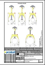
Page 17: ...hin und herschieben bis der Federriegel 1 in das entsprechende Loch einrastet Greifbereichsverstellung muss generell symmetrisch erfolgen Das heißt es muss bei beiden Rechteckrohren jeweils das gleiche Verstellloch verwendet werden Vorsicht bei der Einstellung des Greifbereiches Verletzungsgefahr der Hände Schutzhandschuhe verwenden Abb 1 Abb 2 5 1 1 Einstellung der höhenverstellbaren Auflage Die ...

Page 18: ...lautomatik schaltet bei Entlastung auf Verriegelung wodurch das Gerät wieder angehoben werden kann Greifgüter Betonrohre müssen immer unterhalb des größten Rohrdurchmessers gegriffen werden da ansonsten Abgleitgefahr besteht Greifgüter können wegrutschen oder wegrollen wenn sie im Gefälle auf unbefestigtem oder unebenem Untergrund abgelegt werden Tod und schwere Verletzungen können die Folge sein ...

Page 19: ...Schraubendreher wieder zurück gedrückt werden 1 Gerät ist mit dem Greifgut auf Boden abgesetzt Greifarme werden geöffnet Gerät ist durch das Trägergerät angehoben Greifarme sind geöffnet Abstellposition des Gerätes auf Boden 1 Sonst kann es zu Fehlschaltungen und dann beim Absetzen der Last zur Verformung oder Zerstörung der Wechselautomatik kommen Ruckartiges Anheben oder Absenken des Gerätes sow...

Page 20: ...nachziehen achten Sie darauf dass die Schrauben gemäß den gültigen Anzugsdrehmomenten der zugehörigen Festigkeitsklassen nachgezogen werden Sämtliche vorhandene Sicherungselemente wie Klappsplinte auf einwandfreie Funktion prüfen und defekte Sicherungselemente ersetzen 1 Alle Gelenke Führungen Bolzen und Zahnräder auf einwandfreie Funktion prüfen bei Bedarf nachstellen oder ersetzen Greifbacken so...

Page 21: ...utomatik funktioniert nicht Wechselautomatik mit Hochdruckreiniger reinigen Fehlschaltung korrigieren siehe Kapitel Darstellung der Wechselautomatik Einsatz der Wechselautomatik austauschen 7 3 Reparaturen Reparaturen am Gerät dürfen nur von Personen durchgeführt werden die die dafür notwendigen Kenntnisse und Fähigkeiten besitzen Vor der Wiederinbetriebnahme muss eine außerordentliche Prüfung dur...

Page 22: ... welche maximale Belastung das Gerät ausgelegt ist Die maximale Tragkraft darf nicht überschritten werden Das im Typenschild bezeichnete Eigengewicht ist bei der Verwendung am Hebezeug Trägergerät z B Kran Kettenzug Gabelstapler Bagger mit zu berücksichtigen Beispiel 7 6 Hinweis zur Vermietung Verleihung von PROBST Geräten Bei jeder Verleihung Vermietung von PROBST Geräten muss unbedingt die dazu ...

Page 23: ...Straße 6 Fax 49 7144 3309 50 info probst handling com 71729 Erdmannhausen Germany Betreiber _ _ _ _ _ _ _ _ _ _ _ _ _ _ _ _ _ Gerätetyp _ _ _ _ _ _ _ _ _ _ _ _ _ _ _ _ Artikel Nr _ _ _ _ _ _ _ _ _ _ _ _ _ _ _ Geräte Nr _ _ _ _ _ _ _ _ _ _ _ _ Baujahr _ _ _ _ Wartungsarbeiten nach 25 Betriebsstunden Datum Art der Wartung Wartung durch Firma Stempel Name Unterschrift Wartungsarbeiten alle 50 Betrieb...

Page 24: ......

Page 25: ...5450 0004 V3 GB Operating Instructions RG 8 40 ...

Page 26: ...se 8 3 2 Survey and construction 9 3 3 Technical data 9 4 Installation 10 4 1 Mechanical connection 10 4 1 1 Lifting eye Suspension bolt 10 4 1 2 Load hooks and slings 10 4 1 3 Rotators optional 10 4 1 4 Fork sleeves optional 11 5 Adjustments 11 5 1 Adjustment of the gripping range 11 5 1 1 Adjustment of the height adjustable support 12 6 Operation 12 6 1 Device operation 12 6 2 Picture of the aut...

Page 27: ...inery directive 2006 42 EC The following standards and technical specifications were used DIN EN ISO 12100 Safety of machinery General principles for design Risk assessment and risk reduction ISO 12100 2010 DIN EN ISO 13857 Safety of machinery safety distances to prevent hazard zones being reached by upper and lower limbs ISO 13857 2008 Authorized person for EC documentation Name J Holderied Addre...

Page 28: ...ange and the measure to drive over the gripping good gripping range measure to drive over the gripping good opening width Immersion depth is the maximum gripping height of gripping goods conditional of the height of the gripping arms of the device Device is the description for the gripping device Product dimensions Are the dimensions of the gripping good e g length breadth height of the product De...

Page 29: ... Size Danger of squeezing the hands 2904 0221 2904 0220 2904 0107 30 x 30 mm 50 x 50 mm 80 x 80 mm REGULATORY SIGN Symbol Meaning Order No Size Each operator must have read and understood the operating instructions and all safety instructions 2904 0665 2904 0666 Ø 30 mm Ø 50 mm OPTIONAL Be sure that the fork sleeves are mechanically fixed with locking screw and safety chain or rope to the lifting ...

Page 30: ...orm The workplace must be sufficiently illuminated Take care with handling wet dirty and not solidified components The working with the device in case of atmospheric editions under 3 C 37 5 F is forbidden Because the goods could be fall down caused by dampness or freezing 2 8 Function Control 2 8 1 General Before every usage of the device check the functions and the working condition Maintenance a...

Page 31: ...could fall down The device should not be opened if the opening path of the gripping arm is blocked by a resistance e g other concrete blocks or the like The operator is not allowed to leave the control unit as long as the device loaded with load The load must always be in the range of vision of the operator Never exceed the carrying capacity working load limit WLL and the nominal width gripping ra...

Page 32: ... must ensure that The equipment is suited to the intended operation the functioning and the working condition of the equipment is examined the load is suitable to be handled Any doubts about instructions should be raised with the manufacturer prior to use ATTENTION The use of this device is only permitted in proximity to the ground chapter Safety at work NOT ALLOWED ACTIVITIES Unauthorized alterat...

Page 33: ...r jaws 2 Automatic changeover for fully automatic switching from full to empty 5 Height adjustable support 3 Handle for manual guidance of the device 6 Adjustable gripping range 3 3 Technical data The exact technical data carrying capacity WLL dead weight etc are listed on the type plate data sheet ...

Page 34: ...severe injuries and material damage can result 4 1 1 Lifting eye Suspension bolt The device is equipped with a lifting eye suspension bolt and can be mounted on various carrier lifting devices Take care that the lifting eye suspension bolt is safely joined with the lifting tackle e g crane hook belt and cannot slide down 4 1 2 Load hooks and slings The device is attached to the carrier lifting dev...

Page 35: ...different sizes concrete pipes Before a material to be gripped can be lifted and moved the corresponding gripping range and the height adjustable support must be set The gripping range must never be set on both sides at the same time Always set the gripping range first on one side and then on the other Pull spring bolt 1 upwards and turn by 180 Move the rectangular tube 2 until the gripping range ...

Page 36: ...6 Operation 6 1 Device operation Attach the device RG 8 40 to the carrier hoist using the suspension eye Adjust the opening width gripping range and height adjustable support according to the material to be gripped concrete pipe Position the implement RG 8 40 above the material to be gripped and lower it until the support rests on it As soon as the implement is completely lowered the automatic cha...

Page 37: ...njuries can result Always place gripping goods only on horizontal stable and level ground Always secure pipes against rolling away for example with wedges Without lifting equipment carrier the device may only be parked on even ground The gripping arms must be opened enough to ensure safe standing of the implement Otherwise there is a risk of tipping ...

Page 38: ...ck manually e g with a screwdriver 1 Device is set down with the gripping good on the ground Gripping arms are opening Device is lifted through the lifting equipment carrier Gripping arms are opened laydown position of the device on the ground 1 Otherwise there may be faulty switching and when setting down the load this can cause deformation or damage of the automatic release The jerky lifting and...

Page 39: ...perating hours Tighten all screws and connections take care that the tightening torques according to the property class of the screws are observed Check all existing safety elements such as linchpins for perfect function and replace defective safety elements 1 Check all joints bolts guidance s and gears for correct function if necessary adjust or replace it Check all grippers if available for sign...

Page 40: ... surface of the material or ask the manufacturer if you the material is allowed for this device Unbalanced load The device is not loaded symmetrically Adjust the position of the load Adjustment of the gripping range optional The adjustment of the gripping range is not symmetrical Correct the adjustment of the gripping range Automatic release does not work mechanical optional Automatic release does...

Page 41: ...esponding legal regulations and the regulations of the declaration of conformity must be observed The expert inspection can also be done by the manufacturer Probst GmbH Contact us at service probst handling com We recommend affixing the inspection sticker Sachkundigenprüfung Expert inspection in a clearly visible place order no 2904 0056 Tüv sticker with year number after the inspection has been d...

Page 42: ... can be handled with the device Do not exceed this carrying capacity working load limit WLL If you use the device in combination with other lifting equipment Crane chain hoist forklift truck excavator consider the deadweight of the device Example 7 6 Hints to the renting leasing of PROBST devices With every renting leasing of PROBST devices the original operating instructions must be included unco...

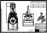
Page 43: ... Achtung Übersicht für Aushubmaße auf Blatt 2 width of trench see sheet 2 4 3 C B A B D F 7 5 1 3 5 7 F 4 2 6 8 E D 8 6 C E 1 2 A Zust Gepr Erst Name von Blatt Ers f Ers d Urspr Artikelnummer Zeichnungsnummer Benennung all rights reserved conform to ISO 16016 5 4 2019 19 1 2012 Ralf Hoffmann I Krasnikov Rohrgreifer RG 8 40 D54500004 1 2 80 400 mm Aussendurchmesser Datum ...

Page 44: ...apacity 430 kg 948 lbs Zust Dokumentenstatus Freigegeben allgemeiner Biegehalbmesser Blechstärke Oberflächen nach DIN EN ISO 1302 Maße DIN EN ISO14405 Fehlende Maße sind dem 3D Modell zu entnehmen Fertigteil ist Maßgebend Name Keine Änderungen ohne Rücksprache mit TB all rights reserved conform to ISO 16016 Artikelnummer Zeichnungsnummer Werkstoff Benennung Änderungstext Datum Urspr Maßstab Datum ...

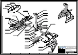
Page 45: ... 20530038 20000008 X X X 20540033 21600002 20000008 X Detail X 20100017 33100011 20400004 20000025 4 3 C B A B D F 7 5 1 3 5 7 F 4 2 6 8 E D 8 6 C E 1 2 A Zust Gepr Erst Name von Blatt Ers f Ers d Urspr Artikelnummer Zeichnungsnummer Benennung all rights reserved conform to ISO 16016 30 1 2019 26 3 2013 Alexander Renger R Seidel Rohrgreifer RG 8 40 E54500004 1 1 80 400 mm Aussendurchmesser Datum ...

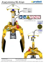
Page 46: ...ert Last changed 07 06 2017 Krasnikov Igor A54500004 RG 8 40 Blatt Sheet 1 1 Einige der Abbildungen sind möglicherweise optionales Zubehör des Gerätes Some of pictures may be optional equipment of the device 29040629 auf beiden Seiten on both sides 29040056 ...

Reviews: