ComBricks User Manual v6.4.0 | January 18| © PROCENTEC
39/219
3.11.1
Screw terminals
•
With a 1 channel repeater module, the channel is marked CH1.
•
With a 2 channel repeater module, the channels are marked CH1 and CH2.
NOTICE
Since March 2014 the
1 Channel
,
2 Channel
and
Scope Repeater
modules are fitted with new, more robust
screw terminals.
Old modules:
The channels (CHx) have 2 screw terminals (IN and OUT, for the bus connection) and a
termination switch.
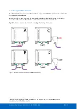
Always use the ‘IN’ connector when the repeater module
is the first or last on the segment. The termination
- configuration A
).
New modules:
The channels have 1 screw terminal and a termination switch. In most cases, the channel
starts here so the termination must be set to ‘ON’. If the channel is not the beginning, use the
DB9
connector, see
paragraph
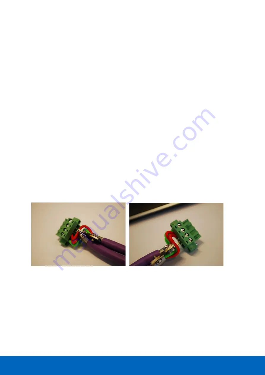
. Alternatively, use the dual ground clip (supplied with the new models) to
install two cables in one screw terminal, see
Only in configuration A of
the on-board termination should be set to ON. In configurations B and D the
repeater module is in the middle of the segment (OFF).
Pin layout of the screw terminals
Pin “A”:
Green wire
Pin “B”:
Red wire
Pin “SH”:
Cable shielding OR
Pin “I”:
Cable shielding
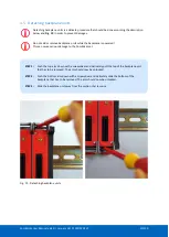
Fig. 26 - Use the Dual Ground Clip to connect two PROFIBUS cables in one screw terminal
Summary of Contents for ComBricks
Page 1: ...User Manual ...
Page 132: ...ComBricks User Manual v6 4 0 January 18 PROCENTEC 132 219 ...
Page 213: ...ComBricks User Manual v6 4 0 January 18 PROCENTEC 213 219 44 Certificates ...
Page 214: ...ComBricks User Manual v6 4 0 January 18 PROCENTEC 214 219 ...
Page 215: ...ComBricks User Manual v6 4 0 January 18 PROCENTEC 215 219 ...
Page 216: ...ComBricks User Manual v6 4 0 January 18 PROCENTEC 216 219 ...
Page 217: ...ComBricks User Manual v6 4 0 January 18 PROCENTEC 217 219 45 Notes ...
Page 218: ...ComBricks User Manual v6 4 0 January 18 PROCENTEC 218 219 ...


