ComBricks User Manual v6.4.0 | January 18| © PROCENTEC
68/219
•
The Min and Max image types per address per module (so a maximum of 2 x 127 per module)
•
Bar Graph (one per module)
•
Error images (maximum 16 per module)
If all images have been saved to SD card, one entry per module will be added to the system log. This makes it
possible to check if an image has been saved to SD card after a certain event or error.
The first 16 error images are saved to SD card. After this, the Scope module saves another 16 images in
memory. These can be saved manually to SD card by clicking on ‘ Refresh scope images’ in the Oscilloscope
Images page of the corresponding module.
The images are saved in an XML-based vector format .svg which can be viewed in any compatible browser.
Recommended is Internet Explorer 9 or higher. You can also find freeware SVG file viewers in the Internet.
The images are located in the following folder on the SD card:
/mmc$/graphs/
You can access the path via any FTP-capable browser, FTP program or simply put the SD-card in your PC (but
make sure the SD card is write-protected when you insert it in the PC). See
paragraph 4.8.3
information.
5.6.1.5
Termination level
For regular Scope Repeater modules you can change the Termination min and max trigger level. This changes
the idle voltage limit. Normally the idle voltage should be around 1V. You can change the sensitivity of this
measurement. If the l
evel is exceeded, the red LED ‘ TERM’ will illuminate.
5.6.1.6
Bargraph OK limit
You can change the
red line in the Bar Graph which is the trigger point for the red ‘MIN’ LED
on the Scope
module. If the installation is very stable with high amplitudes of 4V and more, you could consider raising the
Bargraph OK limit to 3V for example. Or if you have problems with a certain slave which cannot get a higher
amplitude than 2.5V, you can lower the limit to 2V.
5.6.2
Oscilloscope Images
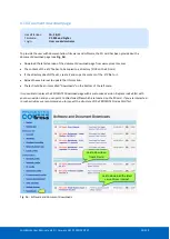
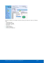
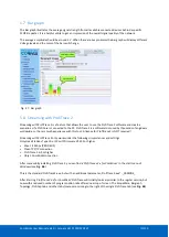
The oscilloscope modules can be viewed by
clicking on the ‘Oscilloscope images’ menu on
the left of the webserver screen.
If more than one module with Scope
functionality has been installed in the
ComBricks, you can select that module in the
drop-down list and see Scope images from
devices connected to that module.
The Image type lets you view the Last, Min or
Max scope image. The Min and Max are the
lowest and the highest measured amplitudes.
Fig. 45 - Oscilloscope images
When the ‘Min’ value drops below the configured ‘Bargraph OK limit’ (default 2.5V) the red LED ‘Min’ will
illuminate on the Scope module. To reset the ‘Min’ and ‘Max’ values simply click the ‘Reset oscilloscope images’
button.
5.6.3
Oscilloscope errors
Whenever an illegal message is seen by ComBricks, and the message occurred on a module with a Scope, you
will be able to find the signal of that illegal message. This is very useful for troubleshooting, because it captures
the moment of a failure. This makes it easy to prove EMC or other cable problems.
Select ComBricks
module and image
type
Summary of Contents for ComBricks
Page 1: ...User Manual ...
Page 132: ...ComBricks User Manual v6 4 0 January 18 PROCENTEC 132 219 ...
Page 213: ...ComBricks User Manual v6 4 0 January 18 PROCENTEC 213 219 44 Certificates ...
Page 214: ...ComBricks User Manual v6 4 0 January 18 PROCENTEC 214 219 ...
Page 215: ...ComBricks User Manual v6 4 0 January 18 PROCENTEC 215 219 ...
Page 216: ...ComBricks User Manual v6 4 0 January 18 PROCENTEC 216 219 ...
Page 217: ...ComBricks User Manual v6 4 0 January 18 PROCENTEC 217 219 45 Notes ...
Page 218: ...ComBricks User Manual v6 4 0 January 18 PROCENTEC 218 219 ...

