ComBricks User Manual v6.4.0 | January 18| © PROCENTEC
95/219
8.8
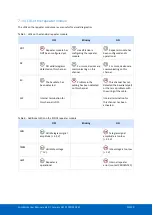
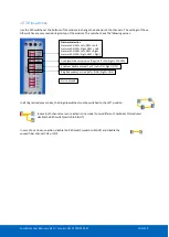
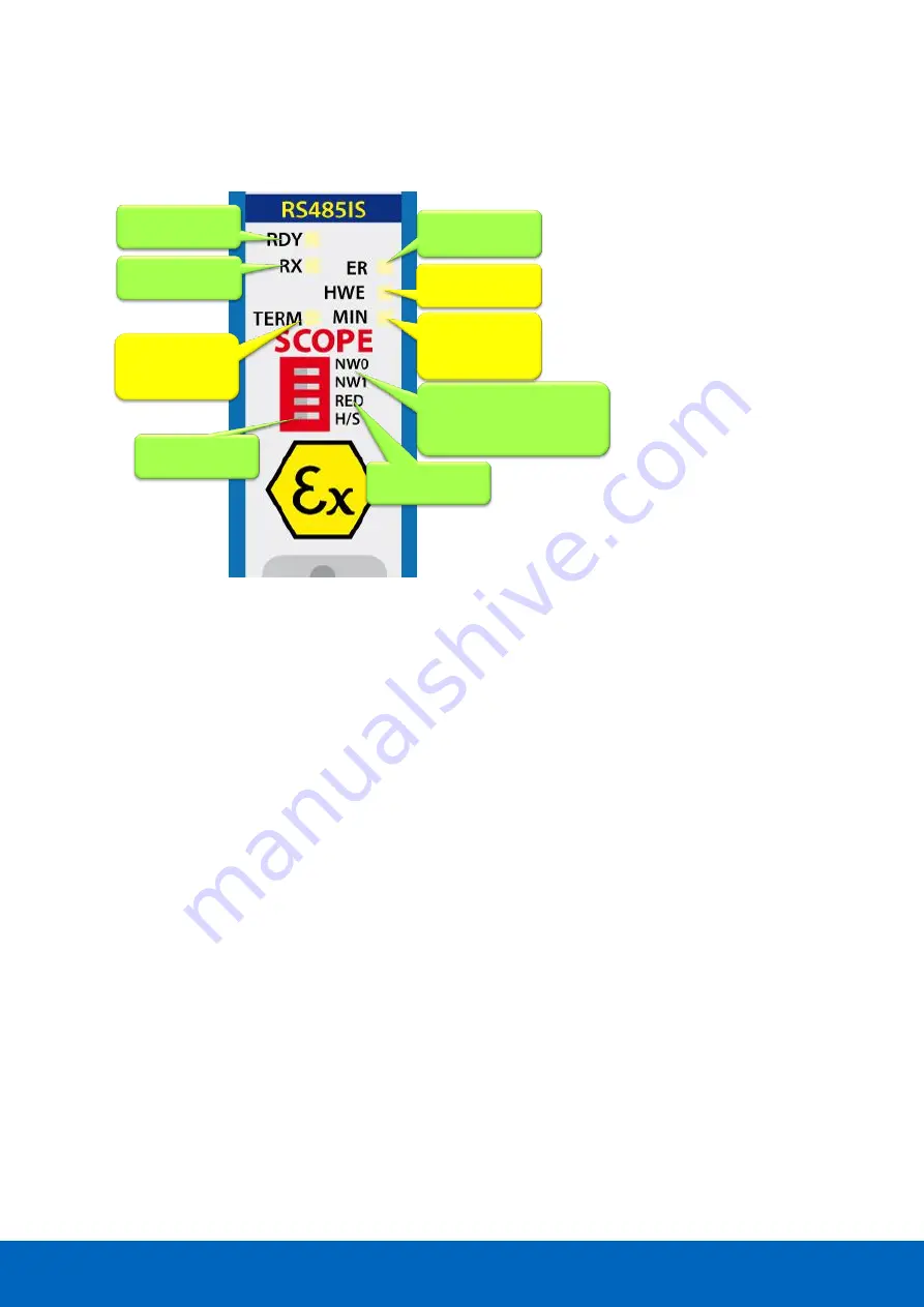
LEDs and DIP switches of the repeater module
The LEDs on the repeater modules are very useful for visual diagnostics.
8.9
Redundancy
Refer to
paragraph 7.9
for a description of the redundancy system.
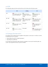
Dipswitches or web
server settings
Redundancy for the
current network
Communication
error or bad
telegrams
Data received
Repeater Module
status
Network 1: NW0 = L, NW1 = L
Network 2: NW0 =
R
, NW1 = L
Network 3: NW0 = L, NW1 =
R
Network 4: NW0 =
R
, NW1 =
R
Repeater internal
failure
The idle voltage
when no station is
sending is
too low
Signal amplitude of
the telegrams
is
too low
Summary of Contents for ComBricks
Page 1: ...User Manual ...
Page 132: ...ComBricks User Manual v6 4 0 January 18 PROCENTEC 132 219 ...
Page 213: ...ComBricks User Manual v6 4 0 January 18 PROCENTEC 213 219 44 Certificates ...
Page 214: ...ComBricks User Manual v6 4 0 January 18 PROCENTEC 214 219 ...
Page 215: ...ComBricks User Manual v6 4 0 January 18 PROCENTEC 215 219 ...
Page 216: ...ComBricks User Manual v6 4 0 January 18 PROCENTEC 216 219 ...
Page 217: ...ComBricks User Manual v6 4 0 January 18 PROCENTEC 217 219 45 Notes ...
Page 218: ...ComBricks User Manual v6 4 0 January 18 PROCENTEC 218 219 ...


