29
© 2012 by Proceq SA
i
Note:
Always deselect the Lock Name attribute once an attribute is placed at the
proper position and before any print, BMP, or display change functions are used
(see Fig. 9.16).
i
Note:
After having added annotations (see section Annotations) to a graph, chang-
ing the units length will cause the annotations to be misplaced. Therefore, before
adding annotations, ensure that the graph has the desired units.
Once you have added annotations, it is recommended that the file is saved. The dimensions of the
graph or the colour scale can then be changed. When changes to the dimensions of the graph are
relatively large, it can occur that label location of the annotation will move. To restore the annotations
correctly, the file can be re-opened.
It is also not recommended that annotations within one file be added at different dimension levels,
i.e. zoom levels.
7 Measuring the electrical resistivity
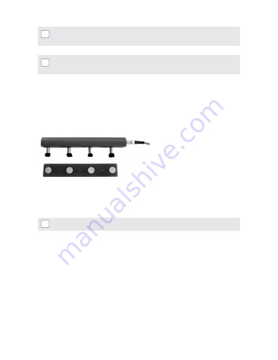
Fig 7.1 Wenner four-point probe with cable and control plate
The four foam pads of the probe should be moistened with water. Connect the resistivity probe to
the INTERFACE RS 232 C of the indicating device and assure that the device is in resistivity mode.
(See 5.3)
Check the configuration of the instrument. (See 5.5)
i
Note:
The Wenner Probe constantly draws current. Therefore it should only be con-
nected to the Indicating Device when measurements are being carried out.
7.1
Preparing the concrete surface for measurement
The concrete surface must not be coated with any electrically insulating coating and it should be
clean. The rebar grid beneath the surface should be marked out with the help of a rebar locator
(e.g. Profometer, Profoscope). The desired measurement grid should be suitably marked out on the
surface and mapped to objects.


