COMPASS-EI–Manual – Chapter 2
Page
15
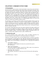
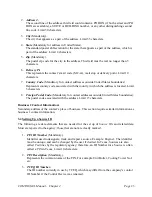
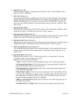
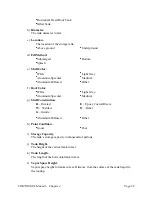
Figure 2.8
Equipment relationships involving control devices are entered in the
Equipment Relationships
screen, as explained earlier. If a control device “feeds” another device that occurs immediately
“downstream” from it, then two relationship records would be expected in this screen. One
record would describe the relationship between a
Source, Point
, and the first
Control
device in
the series. The second record would describe the relationship between the same Source, Point,
and the second
Control
device in the series. In this record, the first device is included under the
column header called “
Feeding
CIN
”. When the “
Feeding CIN
” column is blank in a relationship
record that contains a control device, EI assumes that the flow originates at the Source – not
another
Control
device.
Parallel (as opposed to series) control schemes are easily accommodated by using the
percent
flow
field in the
Equipment Relationships
screen to explain the allocation of flow to each “leg” in
the network. Control schemes that consist of both series and parallel networks can also be
accommodated in EI. Essentially, each node in the control scheme network is explained in an
equipment relationship record with respect to the
Source, Point
, and
Control Device
(s) for that
node.
EI will provide a selection for
Control Devices
that have previously been entered as a
CIN
that
references the
Source
and
Point
which have been designated by the user. Thus, if an equipment
relationship record is being added by the user, and the control device that should be entered is
not available on the drop-down list, the user should cancel the procedure and make sure that a
CIN
has been entered for the desired relationship.
The
Equipment Relationships
screen (
Figure 2.9
) allows relationships for a specific
Source,
Point, or Device
to be produced by selecting the entire
ID Number
or a portion thereof and
clicking on the
List
icon to retrieve only the items corresponding to your selection.


