background image

49

Maintenance

Vacuum Pump Drive Belts

To tighten the vacuum pump belts:

1.

Loosen the four bolts that hold the adjusting plate 
to the frame and the 2 bolts at the back of the belt 
guard.

2.

Turn the adjusting bolts until the proper belt tension 
is achieved (1/4" deflection in the center of the belt, 
halfway between the pulleys).

3.

Retighten all bolts previously loosened.

NOTE: When adjusting belt tension, make certain 
that the engine shaft and vacuum pump shaft remain 
parallel, and the belt tension is equal on both belts.

4.

 Check belt alignment with straightedge.

Make certain that when you re-torque these screws, 
that you use a clockwise pattern and continue until 
proper torque is achieved.

S'assurer, au moment de resserrer ces vis, 
d'utiliser un mouvement de rotation dans le sens 
des aiguilles d'une montre et de continuer jusqu'à 
ce que le couple souhaité soit atteint.


5.

Check for pulley groove wear, clean belts and 
pulley grooves, check for worn belts, proper belt 
tension, and pulley alignment after the first 25 
hours and then again at 100 hours.

Check for belt ride in the groove.

Solution Pump

Refer to the Solution Pump Operation and Service 
Manual for specific instructions.

1.

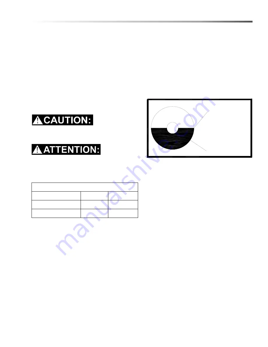
Check the crankcase oil level daily to assure the 
proper level.  Use the illustration as a guide when 
checking the oil level.  If the level has dropped, 
check for the source of leakage and repair. 

2.

Remove yellow filler cap with attached dipstick.  Oil 
level should be between marks on the dipstick or 
use the sight glass located on the non-shaft side of 
the pump.

3.

Change the crankcase oil with GP Pump 
Crankcase Oil, after the first 50 hours of operation. 
Drain and refill the crankcase oil with General 
Pump Crankcase Oil every 500 hours thereafter. 

Oil capacity is 40.6 ounces.

TORQUE VALUES

COMPONENT

INCH/LBS

FOOT/LBS

Engine pulley

360

30

Vacuum pump hub

300

25

RED DOT

OIL LEVEL

WITH UNIT

STOPPED &
ON LEVEL
GROUND

86411100 Manual Operators - Everest E-Idle Prochem

Summary of Contents for EVEREST 408

Page 1: ...146 0 EVEREST 408 HIGH PRESSURE 1 001 151 0 EVEREST 408 LOW PRESSURE 1 001 152 0 EVEREST 650 E IDLE HIGH PRESSURE 1 001 158 0 EVEREST 650 E IDLE LOW PRESSURE 1 001 159 0 EVEREST 408 E IDLE HIGH PRESS...

Page 2: ......

Page 3: ...choice of procedure the skill of the mechanic and the tools or parts available Before attempting any repair make certain that you are thoroughly familiar with this equipment and are equipped with the...

Page 4: ...rements 22 Fuel Requirements 23 Engine Oil Requirements 23 Chemical Requirements 23 Electronic Fuel Injection System 23 Emission Control Information 24 Date Stamp Location 24 Fuel Pump And Filter 24 T...

Page 5: ...e Water Box 50 Pre filter Strainer 50 Waste Tank Vacuum Inlet Filter 50 Solution Screen Outlet 50 Temperature Balance Orifice 50 Check Valve Outlet 51 Chemical Pump 51 Pressure Regulator 51 Vacuum Hos...

Page 6: ...ng items unless otherwise specified and any optional accessories which were ordered NOTE Do not modify unit without written permission from manufacturer Equipment List 1 Console 2 Waste tank 3 Fuel Pu...

Page 7: ...product damage personal injury or severe injury resulting in death The INSTALLATION section contains information on how to properly install the unit in your vehicle The OPERATIONS section is to famil...

Page 8: ...gh speed moving parts such as belts and pulleys should be avoided while this unit is running Severe injury damage or fatality may result DO NOT service this unit while it is running The high speed mec...

Page 9: ...ns We require high back seats on all vehicles in which units are to be installed for head and neck protection We recommend using a metal partition between the seats and equipment DO NOT operate this u...

Page 10: ...roies et les poulies devraient tre vit es durant le fonctionnement de cet appareil Cela pourrait causer des blessures graves des dommages ou la mort NE PAS r parer cet appareil pendant qu il est en ma...

Page 11: ...es baquets dans tous les v hicules dans lesquels des appareils sont install s pour une meilleure protection de la t te et du cou Nous recommandons d utiliser une cloison m tallique entre les si ges et...

Page 12: ...hine damage or faulty operation immediately Do not use the machine if it is not in proper operating condition Following is information that signals some potentially dangerous conditions to the operato...

Page 13: ...d une d t rioration de la machine Ne pas utiliser la machine si celle ci ne fonctionne pas correctement Lire soigneusement les informations ci dessous signalant certains dangers potentiels pour l op r...

Page 14: ...labels NOTE If at any time the labels become illegible promptly replace them REMARQUE Les sch mas ci dessous indiquent l emplacement des plaques de s curit Si les plaques deviennent illisibles les re...

Page 15: ...13 86411100 Manual Operators Everest E Idle Prochem Notes...

Page 16: ...ing in a trailer make certain that trailer is rated for the total weight of UNIT AND TRAILER Electric or hydraulic brakes should be provided and a strict compliance with any State and Federal vehicle...

Page 17: ...illustrations for waste tank and console dimensions Bolting Down Unit And Waste Tank When positioning waste tank with respect to console hook up the vacuum hose from blower to waste tank This will ens...

Page 18: ...16 Installation Layout with 100 Gallon Waste Tank 2 81 2 3 43 4 3 111 8 4 31 8 4 41 8 1 15 8 105 8 5 5 16 5 61 2 3 2 1 16 4 513 16 11 2 1 91 2 65 8 86411100 Manual Operators Everest E Idle Prochem...

Page 19: ...compo nents near the catalytic converter exhaust or any areas of high temperature Avoid any contact with moving parts areas of high temperature brake lines fuel lines muffler catalytic converter or s...

Page 20: ...the vehicle floor at the installation point chosen for the bulkhead 3 Install the 1 8 NPT bulkhead adapter by inserting the adapter and tightening the nut on the opposite side of the van floor 4 Insta...

Page 21: ...ing supplied hose clamps 3 Install 1 1 8P x 5 16 push on hosebarb fitting on to the bulkhead adapter 4 Measure and cut a length of 5 16 fuel hose and connect between the outlet side of the electronic...

Page 22: ...entil s Garder la batterie l cart des tincelles de la flamme nue et de toute autre source d inflammation en tout temps Garder les batteries hors de la port e des enfants Enlever tous les bijoux au mom...

Page 23: ...pressure Optional 3000 PSI maximum Vacuum relief valve 13 Hg Waste tank capacity 100 gallons Console weight Model 408 HP 408 1065 lbs Console weight Model 650 HP 650 1150 lbs Console weight with waste...

Page 24: ...are operating this unit in an area where the unit will be using water in which the hardness exceeds 3 1 2 grains we highly recommend a suitable water softener be installed If using a water softener i...

Page 25: ...and 20W 50 Higher viscosity oils should be used in high temperature operating conditions and lower viscosity oils should be used in cooler tempera ture operating conditions Chemical Requirements This...

Page 26: ...back of the engine block approximately where indi cated Fuel Pump And Filter Your Everest console was shipped to the dealer with a specific fuel pump and fuel filter Ensure that ONLY these items are...

Page 27: ...matically after 20 start run stop cycles if the fault has not been detected DTC Pcode Fault Description CAN SPN CAN FMI Turnson MIL MIL Flash Code Leader Trailer Code 111 1 P0016 CRANK or CAM could no...

Page 28: ...2 41 P0420 Catalyst inactive on gasoline 520211 10 Yes 421 42 P0524 Engine Oil Pressure Too Low 100 1 Yes 524 43 P0562 Battery Voltage Low 168 17 Yes 562 44 P0563 Battery Voltage High 168 15 Yes 563 4...

Page 29: ...P0031 Yes 714 97 P1615 Microprocessor failure A D P0629 P0031 Yes 715 98 P1616 Microprocessor failure Interrupt P0629 P0031 Yes 716 99 P1644 MIL control short to GND P1213 P0004 No 644 100 P1645 MIL...

Page 30: ...CONTROL PANEL PANEL LOWER CONTROL FILTER BOX 12 11 10 9 8 7 6 5 4 3 2 1 Operation High Pressure closed prior to valve must be pump isolation pump Chemical damage chemical system will High pressure 13...

Page 31: ...igh Pressure Solution Outlet Option The high pressure solution outlet is the connecting point for the high pressure washing hose This outlet is a quick disconnect that allows the pressure washing hose...

Page 32: ...30 Operations Upper Control Panel 15 20 3 10b 1 2 4 18 5 17 6 16 15 14 7 13 8 12 11 10a 9 86411100 Manual Operators Everest E Idle Prochem...

Page 33: ...ll continue to run To turn power off rotate key counter clockwise to stop position engine will then stop 8 Circuit Breakers These serve to protect the circuits from electrical spike and over loads and...

Page 34: ...nergize the magnetic clutch to turn the solution pump on or off Turn clockwise for activating the pump and counter clockwise for deacti vating the pump Filter Box 1 Vacuum Inlets The vacuum inlets ser...

Page 35: ...the cleaning water during the exchange process creating a very efficient transfer of heat out of the engine and into the cleaning water The third stage of plumbing and heat exchange takes place in the...

Page 36: ...34 Operations 86411100 Manual Operators Everest E Idle Prochem...

Page 37: ...35 Operations 86411100 Manual Operators Everest E Idle Prochem...

Page 38: ...hemical can be directed to the metering valve The metering valve controls the amount of chemical that enters the solution outlet manifold The manifold assembly s check valve will not allow the chemica...

Page 39: ...s of changes in direction and velocity The air is then filtered and rushes into the vacuum pump The vacuum pump compresses and heats the incoming air The hot discharged air is forced down stream into...

Page 40: ...se to the water supply faucet NOTE Never use your waste pump outlet hose as a water inlet hose Use only clean hoses for water inlet 2 Turn the water supply faucet on The water will fill the water box...

Page 41: ...ete NEVER dispose of waste in storm drains water ways or on ground areas Always dispose of waste in accordance with Local State and Federal laws NE JAMAIS liminer les r sidus dans les collec teurs d e...

Page 42: ...he high pressure system NEVER use your low pressure system hoses with the high pressure system Prochem offers a special high pressure hose rated for pressure washer activities Only use Prochem approve...

Page 43: ...eaning operations in that no water or solution is required An automatic waste pump out is highly recommended for all de flooding operations due to the large amount of water removal often required 1 Mo...

Page 44: ...hment P N 86260700 to the bottom solution outlet connection and the water inlet connection Turn the solution pump switch ON Allow the unit to run for approximately 3 minutes with the winterizing loop...

Page 45: ...flow into the other side of the system High Pressure Optional Close ball valve between chemical pump and solution pump Move pressure system valve to high pressure position Open the tool valve and drai...

Page 46: ...perature Balance Orifice Weekly Remove clean and check screen Battery Weekly Check for proper fluid level Fill with distilled water only Solution Outlet Screen Bi Weekly Inspect and remove any debris...

Page 47: ...rque values Re torque if required Drive Pulley 500 hrs Inspect clean and check for pulley groove wear Drive Pulley 500 hrs Check pulley alignment Drive Belts 500 hrs Replace Drive Belts 500 hrs Check...

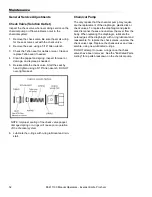
Page 48: ...o keep your chemical system functioning properly follow the chemical pump and solution outlet maintenance in the Maintenance Schedule in this manual Refer any additional questions to your dealer Heat...

Page 49: ...ican Petroleum Institute service class SH The recommended SAE viscosity grades are 10W 40 or 15W 40 for regular oil Recommended viscosity grades for synthetic oil are 10W 30 10W 40 15W 50 and 20W 50 N...

Page 50: ...the unit at least 1 minute to remove any moisture from the vacuum pump 3 Fill the lubrication cup with water displacing lubri cant for 5 seconds while the unit is running and the vacuum inlets are se...

Page 51: ...Check for pulley groove wear clean belts and pulley grooves check for worn belts proper belt tension and pulley alignment after the first 25 hours and then again at 100 hours Check for belt ride in th...

Page 52: ...eplace if needed See the Illus trated Parts Listing for a parts break down Pre filter Strainer The strainer basket located inside the pre filter box should be removed and cleaned whenever it is full o...

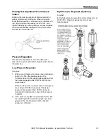
Page 53: ...rated at 4000 PSI NE PAS tenter de r parer les flexibles solution haute pression Tenter de r parer des flexibles solution haute pression pourrait causer des br lures et des blessures graves All high...

Page 54: ...f the check valve poppet damaged spring or o rings will cause poor operation of the chemical system 6 Lubricate the o rings with o ring lubricant and rein stall Chemical Pump The only repairs that the...

Page 55: ...h your unit running tool valve open and solution pump on check the pressure gauge We recommend setting the pressure regulator so that the pressure gauge reads 450 PSI with the tool valve closed When t...

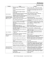
Page 56: ...fill a gallon container about every 17 seconds at high speed Examine the check valves plunger cups and cylinder head on the solution pump Repair whenever required refer to the solution pump service ma...

Page 57: ...clog the strainer If damaged replace Suction leak in the inlet tube leading into the chemical pump Inspect inlet tube and flow meter for damage and replace if required Chemical pump check valve s is c...

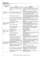
Page 58: ...e starter motor If necessary replace Vacuum pump seized Refer to Gardner Denver Service Repair Manual or dealer Starter turns over engine but will not start Waste tank is full Empty the waste tank Def...

Page 59: ...et Adjust lever Automatic waste pump is malfunctioning or not operating normally NOTE When replacing the pump or float switch on internal in tank pumpout use new electrical connectors and heat shrink...

Reviews: