MAINTENANCE
EVEREST 980086 06/26/03
4-3
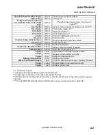
KEY CHECKPOINTS
Note: Initiation of a planned preventative
maintenance program will assure that your unit
has optimum performance, a long operating life,
and a minimal amount of "down" time.
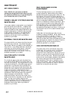
ENGINE COOLANT SYSTEM (RADIATOR)
MAINTENANCE
Your engine radiator coolant system is an important
part of the power plant operation. In addition, this
heat exchange system is used to provide heat for
cleaning operations is also highly dependent on the
engine coolant system. Follow the recommended
coolant system maintenance in the Maintenance
Schedule in this manual and your Nissan A-15
engine owner’s manual. Refer any additional
questions to your dealer.
EXTERNAL FUEL PUMP MAINTENANCE
The power plant for unit receives fuel from the main
gas tank of your van/truck. An external fuel pump
that provides this fuel is located on the underside of
the van/truck. Loose fittings and hose connections
will cause your unit to perform poorly. Follow the
recommended fuel pump maintenance in the
Maintenance Schedule in this manual. Refer any
additional questions to your dealer.
SOLUTION SUPPLY SYSTEM
MAINTENANCE
The chemical supply system pulls chemicals from
your chemical bottle utilizing a pump that works off
the water pump pulsing. Any clogged filters or loose
connections will result in a chemical supply system
malfunction or a malfunction at the cleaning tool.
Maintenance of the solution outlet check valve and
strainer are vital to effective cleaning operation and
minimal unit downtime. Additionally, the hoses
related to supplying water and chemical to the outlet
manifold are under high pressures and experience
thermal expansion and contraction. Periodic
inspections of these hoses for tears, cracks, and
failing connectors are necessary to avoid unwanted
leaks. To keep your solution supply system
functioning properly, follow the chemical pump and
solution outlet maintenance in the Maintenance
Schedule in this manual. Refer any additional
questions to your dealer.
HEAT EXCHANGER SYSTEM
MAINTENANCE
The heat exchange system in your unit transfers
energy between the unwanted heat of the power
plant and the solution supply system of the unit. The
heat transfer of this system is highly dependent on
the surface area contact in the heat exchanger cores
located in the heat exchanger box. This surface area
amount is adversely minimized when the supplied
water is not softened to recommended levels. Hard
water will result in scaling on the inside walls of the
heat exchanger tubes. It is recommended that you
use a dealer approved water softener to avoid
premature heat exchanger core failure. Contact your
local dealer for advice on the water hardness levels
in your area.
Additionally, the heat exchanger tubes are very
sensitive to freezing conditions. As the water freezes
during cold conditions, it expands in the heat
exchanger tubes and causes damage. Often the
tubes are cracked and require the replacement of the
heat exchanger core. Refer to the Freeze Protection
instructions section in this manual. Refer any
additional questions to your dealer.
VACUUM PUMP MAINTENANCE
The total function of the unit is based around the
performance of the vacuum pump. Heat transfer
used to raise the temperature of the solution is
gained from the air drawn by the vacuum pump and
solution is removed from the carpet with the vacuum
suction of the vacuum pump. General maintenance
actions for the vacuum pump as listed in this manual
are vital to prolonged vacuum pump operations.
Daily lubrication of the pump is required to avoid
seizure of the system. Also, waste tank filters and
strainers must be maintained to prevent unwanted
debris from entering the vacuum pump.
Summary of Contents for EVEREST HP
Page 28: ...NOTES EVEREST 980086 02 18 03 3 19 THIS PAGE LEFT BLANK INTENTIONALLY...
Page 53: ...CHEMICAL CONTROL PANEL EVEREST 980086 02 18 03 5 9 11 1 2 4 5 6 7 8 9 10 1 2 3 7 7 12 13 14...
Page 59: ...ENGINE EVEREST 980086 02 18 03 5 15 7 5 6 7 8 4 3 1 2 9 12 5 6 7 SUPPLIED WITH ENGINE 13...
Page 63: ...ENGINE GOVERNOR EVEREST 980086 02 18 03 5 19 4 5 3 2 1 9 6 4 5 7 10 11 12 11 13 14 15 16...
Page 77: ...SOLUTION TEMPERATURE CONTROL VALVE EVEREST 980086 12 16 03 5 33 2 3 4 6 5 7 4 1...
Page 95: ...BATTERY FLOOR MOUNT EVEREST 980086 06 07 03 5 51 3 1 2 4 8 6 5 7 10 2 2 9...


