background image

www.usaprocom.com

15

200088-01A

INSTALLATION

Use only logs supplied with heater. Each 

log is marked with a number. This number 

will  help  you  to  identify  the  logs  when 

installing.  Do  not  place  any  decorative 

cinders on logs or burner.

1.  Remove  the  packing  material  from  the 

logs. The log number is marked on the 

back of each log.


Refer to Figure 16 for log placement.

2.  Place pins on log #1 into two slots in the 

rear bracket.

3.  Place pin on log #2 into slot on left side of 

the middle bracket.

4.  Place pin on log #3 into slot on right side 

of the middle bracket.

5.  Install hole in log #4 onto pin on the left side 

of log #1, with one end resting on log #2.

6.  Install hole in log #5 onto pin on the right 

side of log #1, with one end resting on 

log #3.

IMPORTANT:

 Make sure logs do not cover 

any burner ports. It is very important to install 

the logs exactly as instructed. Do not modify 

logs. Use only logs supplied with heater.

  WARNING:  Failure  to  posi-

tion  the  parts  in  accordance 

with  these  diagrams  or  failure 

to  use  only  parts  specifically 

approved with this heater may 

result  in  property  damage  or 

personal injury.

 CAUTION: After installation, 

and  periodically  thereafter, 

check  to  ensure  that  no  flame 

comes in contact with any log. 

With the heater set to high, check 

to see if flames contact any log. If 

so, reposition logs according to 

the log installation instructions 

in this manual. Flames contact-

ing logs will create soot.

It is very important to install the logs ex-

actly  as  instructed.  Do  not  modify  logs. 

INSTALLING LOGS

Rear Bracket

Log #1

Log #2

Log #4

Log #5

Log #3

Middle Bracket

Figure 16 - Log Installation

Summary of Contents for QD250T

Page 1: ...itch do not use any phone in your building Immediately call your gas supplier from a neighbor s phone Follow the gas supplier s instructions If you cannot reach your gas supplier call the fire department Installation and service must be performed by a quali fied installer service agency or the gas supplier WARNING This appliance is equipped for natural and propanegas Fieldconversionisnotpermittedo...
Page 2: ...tecombustionandventilationairmustbeprovided Refer to Air For Combustion and Ventilation section on page 7 of this manual WARNING Improper installation adjustment al teration service or maintenance can cause injury or property damage Refer to this manual for correct in stallation and operational procedures For assistance or additional information consult a qualified installer service agency or the ...

Page 3: ...nce of alcohol and those at high altitudes NATURALAND PROPANE LP GAS Natural and Propane LP gas are odorless An odor making agent is added to the gas The odor helps you detect a gas leak However the odor added to the gas can fade Gas may be present even though no odor exists WARNING Any change to this heater or its controls can be dangerous WARNING Do not allow fans to blow directly into fireplace...

Page 4: ...levations of 4 500 feet could cause pilot outage 11 To prevent performance problems do not use propane LP fuel tank of less than 100 lbs capacity 12 Do not use this heater as a wood burning heater Use only the logs provided with the heater 13 Solid fuels should not be burned in a heater in which a vent free log set is installed Do not use this heater to cook food or burn paper or other objects 14 ...

Page 5: ...room tem perature 2 GAS OPTIONS AVAILABLE Your heater is equipped to operate on either Propane LP or Natural gas The heater is shipped from the factory ready for connect ing to Propane LP The heater can easily be changed to Natural gas by having your quali fied installer follow the instructions on page 9 and the markings on the heater LOCAL CODES Install and use heater with care Follow all local c...

Page 6: ...on air and circulation air 2 If high humidity is experienced a dehu midifier may be used to help lower the water vapor content of the air 3 Do not use an unvented room heater as the primary heat source UNPACKING 1 Remove top inner pack 2 Tilt carton so that heater is upright 3 Remove protective side packaging 4 Slide heater out of carton 5 Remove protective plastic wrap 6 Remove two screws in the ...

Page 7: ...g appli ances WARNING This heater shall not be installed in a room or space unless the required vol ume of indoor combustion air is provided by the method de scribed in the National Fuel Gas Code ANSI Z223 1 NFPA 54 the International Fuel Gas Code or applicable local codes WARNING Iftheareainwhich theheatermaybeoperateddoes notmeettherequiredvolumefor indoorcombustionair combus tion and ventilatio...

Page 8: ... Air Inlet Air Inlet Air Ventilated Crawl Space To Crawl Space To Attic INSTALLATION NOTICE This heater is intended for use as supplemental heat Use this heater along with your primary heating system Do not install this heater as your pri mary heat source If you have a centralheatingsystem youmay run system s circulating blower whileusingheater Thiswillhelp circulatetheheatthroughoutthe house In t...

Page 9: ...mbustible side wall should not be less than 12 B Clearances from the heater to the ceiling should not be less than 48 C Clearance from heater to back wall should not be less than 6 GAS SELECTION This appliance is factory preset for propane LP gas No changes are required for connecting to propane LP Only a qualified installer or service technician can perform gas selection and connecting to gas sup...

Page 10: ...lection device and reinstall screws 4 Remove hex plug with wrench provided from natural gas inlet of regulator and discard see Figure 7 Install gas line into NG inlet of regulator Use thread sealant to assure there are no leaks Fuel Selector Knob Fuel Selector Knob Hex Plug Hex Plug Figure 8 Settings for Propane LP Gas Selection Gas Connection Fitting Gas Connection Fitting Back of Stove Back of S...

Page 11: ... Installa tion must include an equipment shutoff valve union and plugged 1 8 NPT tap Locate NPT tap within reach for test gauge hook up NPT tap must be upstream from heater see Figure 10 page 12 IMPORTANT Install an equipment shutoff valve in an accessible location The equip ment shutoff valve is for turning on or shutting off the gas to the appliance WARNING A qualified ser vice technician must c...

Page 12: ...vent down protects it from freezing rain or sleet Install sediment trap in supply line as shown in Figure 10 Place sediment trap where it is within reach for cleaning Place sediment trap where trapped matter is not likely to freeze A sediment trap traps moisture and contami nants This keeps them from going into heater controls If sediment trap is not installed or is installed wrong heater may not ...

Page 13: ...joints Ifbubblesform there is a leak Correct all leaks at once PRESSURE TESTING GAS SUPPLY PIPING SYSTEM Test Pressures In Excess Of 1 2 PSIG 3 5 kPa 1 Disconnect heater with its appliance main gas valve control valve and equipment shutoff valve from gas supply piping sys tem Pressures in excess of 1 2 PSIG will damage heater regulator 2 Cap off open end of gas pipe where equip ment shutoff valve ...

Page 14: ...ht heater see Lighting Instructions on page 16 Check all other internal joints for leaks 7 Turn off heater see To Turn Off Gas Ap pliance page 17 AAA Battery Positive UP BATTERY INSTRUCTIONS CAUTION Do not dispose of batteries in fire batteries may explode or leak Battery is included Remove battery when depleted Only install or replace with a AAA battery Be sure to observe proper polarity when ins...

Page 15: ... side of log 1 with one end resting on log 3 IMPORTANT Make sure logs do not cover any burner ports It is very important to install the logs exactly as instructed Do not modify logs Use only logs supplied with heater WARNING Failure to posi tion the parts in accordance with these diagrams or failure to use only parts specifically approved with this heater may result in property damage or personal ...

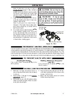
Page 16: ...ith the screen in place Make sure screen is installed before running heater NOTICE Duringinitialoperationof new heater burning logs will give offapaper burningsmell Orange flame will also be present Open damper or window to vent smell This will only last a few hours 1 STOP Read the safety information above 2 Make sure equipment shutoff valve is fully open 3 Turn control knob clockwise to the OFF p...

Page 17: ...ot After 30 seconds release control knob 5 Make sure the heater screen is in place before operating heater TO TURN OFF GAS TO APPLIANCE MANUAL LIGHTING PROCEDURE Note If pilot does not stay lit refer to Troubleshooting page 21 Also contact a qualified service technician or gas supplier for repairs Until repairs are made light pilot with match To light pilot with match see Manual Lighting Procedure...

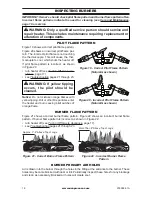
Page 18: ... Off Gas to Ap pliance page 17 see Troubleshooting pages 21 through 23 WARNING If yellow tipping occurs the pilot should be cleaned Notice Do not mistake orange flames with yellow tipping Dirt or other fine particles enter the heater and burn causing brief patches of orange flame Approx 3 6 Above Top of Logs More Than 8 Above Top of Logs Approx 3 6 Above Top of Logs More Than 8 Above Top of Logs F...

Page 19: ...ir Inlet Holes BURNER INJECTOR HOLDER AND PILOT AIR INLET HOLE We recommend that you clean the unit ev ery 2 500 hours of operation or every three months We also recommend that you keep the burner tube and pilot assembly clean and free of dust and dirt To clean these parts we recommend using compressed air no greater than 30 PSl Your local computer store hardware store or home center may carry com...

Page 20: ...With the unit off lightly blow air through the air inlet hole You may blow through a drinking straw if compressed air is not available Figure 23 Pilot Inlet Air Hole Pilot Air Inlet Hole Natural Gas Burner Propane LP Gas Burner Pilot Air Inlet Hole CARE AND MAINTENANCE ODS PILOT CABINET Air Passageways Use a vacuum cleaner or pressurized air to clean Exterior Use a soft cloth dampened with a mild ...

Page 21: ... trode is broken 2 Ignitor electrode is not con nected to ignitor cable 3 Ignitor cable is pinched or wet 4 Broken ignitor cable 5 Bad piezo ignitor 6 Low battery 1 Replace electrode 2 Replace ignitor cable 3 Free ignitor cable if pinched by any metal or tubing Keep ignitor cable dry 4 Replace ignitor cable 5 Replace piezo ignitor 6 Replace battery When ignitor button is pressed in there is a spar...

Page 22: ...t is lit 1 Burner orifice is clogged 2 Burner orifice diameter is too small 3 Inlet gas pressure is too low 1 Clean burner orifice see Care and Maintenance page 19 or replace burner orifice 2 Replace burner orifice 3 Contact local gas supplier Delayed ignition of burner s 1 Manifold pressure is too low 2 Burner orifice is clogged 1 Contact local gas supplier 2 Clean burner see Care and Maintenance...

Page 23: ...adjacent walls or furniture 1 When heated the vapors from furniture polish wax carpet cleaners etc turn into white powder residue 1 Turn heater off when using furniture polish wax carpet cleaner or similar products Heater produces un wanted odors 1 Heater is burning vapors from paint hair spray glues etc See IMPORTANT statement page 21 2 Gas leak See Warning State ment at the top of page 21 3 Low ...

Page 24: ...s malfunctioning Type of gas used Propane LP or Natural gas NG Purchase date Usually we will ask you to return the defective part to the factory PARTS NOT UNDER WARRANTY Contact authorized dealers of this product If they can t supply original replacement part s call Customer Service toll free at 1 866 573 0674 for referral information When calling Customer Service have ready Model number of your h...

Page 25: ...ied heat propane LP gas supply might be low propane LP units only You may feel your gas pressure is too low If so contact your local gas supplier TECHNICAL SERVICE You may have further questions about installation operation or troubleshooting If so contact ProCom Heating Inc at 1 866 573 0674 When calling please have your model and serial numbers of your heater ready ...

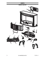
Page 26: ...www usaprocom com 200088 01A 26 PARTS MODEL QD250T 5 7 8 10 11 12 6 9 1 2 3 4 18 15 16 14 17 13 ...

Page 27: ...6 Door 1 5 NDD0308 400 ODS Pilot 1 6 ML073 04 Igniter Cable 1 7 YDF06 QD250T Fuel Selection Device Assembly 1 8 MDL304B Selector Knob 1 9 PIMSC1 01 Piezo Ignitor 1 10 RV83FI 4 9 Regulator 1 11 PF120820 Regulator Plug 2 12 SIT545 200 Control Valve 1 13 QL019 01A 01 Leg 4 FB28D500 B Log Set 1 14 FB28D501 B Log 1 1 15 FB28D502 B Log 2 1 16 FB28D503 B Log 3 1 17 FB28D504 B Log 4 1 18 FB28D505 B Log 5 ...

Page 28: ...ctions furnished with the unit WHAT IS NOT COVERED This warranty does not apply to parts that are not in original condition because of normal wear and tear or parts that fail or become damaged as a result of misuse accidents lack of proper maintenance or defects caused by improper installation Travel diagnostic cost labor transportation and any and all such other costs related to repairing a defec...
Reviews: