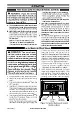
background image

www.usaprocom.com

200204-01B

10

INSTALLATION

Gas Inlet / Gas esté

INLET GAS PRESSURE MAX 1/2 PSIG (3.5 KPa)

200110-01B

03/15

WARNING: 

Make sure Regulator Cap is in the appropriate position 

as shown in diagrams. Installation and service should be done by 

qualified service technician only.

Natural Gas

When using natural gas:

   Make sure the cap is installed in the propane/LP inlet of regulator.


Use thread sealant to assure there are no leaks.

Propane/LP Gas

When using propane/LP gas:

   Make sure the cap is installed in the natural gas (NG) inlet of regulator.


Use thread sealant to assure there are no leaks.

ADVERTENCIA: 

Asegúrese la tapa del regulador esté en la posición adecuada, 

como se muestra en los diagramas. La instalación y reparaciones deben ser realizadas 

por un técnico de servicio calificado solamente.


Gas Natural 

Cuando se utiliza gas natural: 

   Asegúrese de que la tapa está instalado en el propano/LP entrada del regulador. 

   Utilice sellador de roscas para asegurar que no haya fugas. 

Propano/LP Gas 

Cuando se utiliza el gas propano / LP: 

    Asegúrese de que la tapa está instalado en la entrada de gas natural (GN) del regulador. 

    Utilice sellador de roscas para asegurar que no haya fugas.

Correct Pilot Flame Pattern

Incorrect Pilot Flame Pattern

NG

3-3.5" WC

Natural Gas

Shown

LP

8-11" WC

NG

3-3.5" WC

Natural Gas

Shown

LP

8-11" WC

1/2 Glass

Height

1/2 Glass

Height

Yellow

Tipping

Correct Burner Flame Pattern

Incorrect Burner Flame Pattern

LP

Blue Plunger

INSTALL SUPPLIED CAP IN FITTING

NOT BEING USED.

INSTALAR TAPA SUMINISTRADA MONTAJE NO SE UTILIZA.

NG

Yellow Plunger

This appliance may be installed in an aftermarket,* 

permanently located, manufactured (mobile) home, where 

not prohibited by local codes.

This appliance is only for use with propane or natural gas.

Field conversion by any other means including the use of 

a kit is not permitted.

WARNING: Make sure the supplied cap is 

installed in unused regulator fitting before 

connecting the correct gas supply line. 

WARNING: Do not use natural gas and 

propane gas together.

CAUTION: Two gas line installations at 

the same time are prohibited.
ADVERTENCIA: Asegúrese de que la línea 

no utilizado se conecta por primera vez 

antes de conectar la línea de suministro 

de gas correcta. 

ADVERTENCIA: No utilice el gas natural y 

el gas propano juntos.

PRECAUCIÓN: Dos instalaciones de 

líneas de gas al mismo tiempo están 

prohibidos.

FOR PROPANE GAS SUPPLY

PARA LA FUENTE DE GAS DEL PROPANE

CAUTION: The heater requires an external regulator to reduce 

the LP tank pressure to a maximum of 14" W.C. Never connect 

this product directly to the supply tank.
PRECAUCIÓN: El calentador requieres una externa regulador 

para reducir la presión del tanque de gas a un máximo de 14" 

W.C. Nunca conecte este producto directamente al tanque de 

suministro.

FOR NATURAL GAS SUPPLY

PARA LA FUENTE DE GAS DEL NATURAL

NOTICE: An additional gas regulator will be necessary if the 

local natural gas pressure exceeds the heater's rated maximum 

inlet pressure. If in doubt, contact the local gas utility. If natural 

gas inlet pressure exceeds 10" W.C., the safety pressure switch 

will activate. See owners manual for proper procedure to bypass 

the pressure switch.
AVISO: Un regulador de gas adicional será necesario si la 

presión del gas natural local excede de entrada nominal máxima 

del calentador presión. En caso de duda, póngase en contacto 

con la compañía de gas local. Si la presión de entrada de gas 

natural supera los 10" WC, el interruptor de presión de 

seguridad se activará. Consulte el manual del propietario para el 

procedimiento adecuado de derivación el interruptor de presión.

Procom Heating, Inc. U.S. Patent Information

This product may be covered by one or more of the following

United States patents:

8,915,239   8,851,065   8,764,436   8,757,202   8,757,139   8,752,541   

8,568,136   8,545,216   8,517,718   8,516,878   8,506,290   8,465,277   

8,317,511   8,297,968   8,281,781   8,241,034   8,235,708   8,152,515   

8,011,920   7,967,006   7,967,007   7,654,820   7,730,765   7,677,236   

7,607,426   7,434,447

Other patents pending.

TOLL-FREE Customer Care Number: 1-866-573-0674

Numero de Atención al Cliente GRATUITO: 1-866-573-0674

Visit our website for more information www.usaprocom.com

Visite nuestra página web para más informacion www.usaprocom.com

Figure 7 - Back of Stove

Gas Connection

Yellow Natural Gas 

Plunger Underneath 

Metal Cap

Blue Propane/LP Gas 

Plunger Underneath 

Dust Cover

Figure 8 - Gas Regulator

Insert Gas Fitting 

for Natural Gas

Insert Gas Fitting 

for Propane/LP Gas

Blue Dust Cover

DO NOT REMOVE

Blue Propane/LP 

Plunger

Install Gas Fitting Here

GAS SELECTION

This appliance is factory 

preset for propane/LP gas. 

No changes are required for 

connecting to propane/LP.


Only a qualified installer or service 

technician can perform gas selec-

tion and connecting to gas supply.

 CAUTION: Two gas line in-

stallations at the same time are 

prohibited.

 CAUTION: To avoid gas leak-

age for the gas not being used at 

the inlet of regulator, a qualified 

installer or service technician 

must use supplied cap.
You will notice a color coded 

plunger on the inside of the regu-

lator. This is normal. When the in-

let connection fitting is inserted 

and tightened, this plunger will 

be  pushed  back  by  the  fitting 

making  all  of  the  adjustments 

for the gas being supplied. DO 

NOT REMOVE THE PLUNGER. 

The regulator will not work.

The inlet regulator is color coded 

for identification of the correct 

gas type. Blue is for propane (LP 

gas) and yellow is for natural gas.

FOR PROPANE/LP GAS 

INSTALLATION: BLUE

1.  Remove blue dust cover.

Summary of Contents for QNSD250RT

Page 1: ...his or any other appliance WHAT TO DO IF YOU SMELL GAS Do not try to light any appliance Do not touch any electrical switch do not use any phone in your building Immediately call your gas supplier from a neighbor s phone Follow the gas supplier s instructions If you cannot reach your gas supplier call the fire department Installation and service must be performed by a quali fied installer service ...

Page 2: ... which it is installed Provisions for ad equatecombustionandventilationairmustbeprovided Refer to Air For Combustion and Ventilation section on page 7 of this manual WARNING Improper installation adjustment al teration service or maintenance can cause injury or property damage Refer to this manual for correct in stallation and operational procedures For assistance or additional information consult...

Page 3: ...ence of alcohol and those at high altitudes NATURALAND PROPANE LP GAS Natural and Propane LP gas are odorless An odor making agent is added to the gas The odor helps you detect a gas leak However the odor added to the gas can fade Gas may be present even though no odor exists WARNING Any change to this heater or its controls can be dangerous WARNING Do not allow fans to blow directly into fireplac...

Page 4: ...ld cause pilot outage 11 To prevent performance problems do not use propane LP fuel tank of less than 100 lbs capacity 12 Do not use this heater as a wood burning heater Use only the logs provided with the heater 13 Solid fuels should not be burned in a heater in which a vent free log set is installed Do not use this heater to cook food or burn paper or other objects 14 To prevent sooting follow t...

Page 5: ...ater can easily be changed to Natural gas by having your quali fied installer follow the instructions on page 10 and the markings on the heater LOCAL CODES Install and use heater with care Follow all local codes In the absence of local codes use the latest edition of The National Fuel Gas Code ANSI Z223 1 NFPA 54 Available from American National Standards Institute Inc 25 West 43rd Street New York...

Page 6: ...n air 2 If high humidity is experienced a dehu midifier may be used to help lower the water vapor content of the air 3 Do not use an unvented room heater as the primary heat source UNPACKING 1 Remove top inner pack 2 Tilt carton so that heater is upright 3 Remove protective side packaging 4 Slide heater out of carton 5 Remove protective plastic wrap 6 Hold the screen lift and pull forward 7 Remove...

Page 7: ...g appli ances WARNING This heater shall not be installed in a room or space unless the required vol ume of indoor combustion air is provided by the method de scribed in the National Fuel Gas Code ANSI Z223 1 NFPA 54 the International Fuel Gas Code or applicable local codes WARNING Iftheareainwhich theheatermaybeoperateddoes notmeettherequiredvolumefor indoorcombustionair combus tion and ventilatio...

Page 8: ...t to vinyl or cloth wall coverings or operating heater where impurities such as to baccosmoke aromaticcandles cleaning fluids oil or kerosene lamps etc in the air exist may cause walls to discolor Ventilation Air From Outdoors Figure 5 Ventilation Air from Outdoors Provide extra fresh air by using ventilation grills or ducts You must provide two perma nent openings one within 12 of the ceiling and...

Page 9: ...ining wall Measure from outermost point of heater This heater is designed to sit directly on the floor or on a mantel base IMPORTANT You must maintain minimum wall and ceiling clearances during installation The minimum clearances are shown in Figure 6 Measure from outermost point of heater If installed on carpeting or other combustible material other than wood a floor protector made of metal or wo...

Page 10: ...xterna regulador para reducir la presión del tanque de gas a un máximo de 14 W C Nunca conecte este producto directamente al tanque de suministro FOR NATURAL GAS SUPPLY PARA LA FUENTE DE GAS DEL NATURAL NOTICE An additional gas regulator will be necessary if the local natural gas pressure exceeds the heater s rated maximum inlet pressure If in doubt contact the local gas utility If natural gas inl...

Page 11: ...ff the shelfpipeplug Thiscandamage theplunger Thesuppliedregula tor cap is designed so it will not engage the unused gas type 4 Apply thread sealant to the threads on the connection fitting While pushing in rotate the fitting clockwise until the threads engage the regulator After the fitting has been hand tightened into the regulator use a wrench to complete tightening of the fitting Install addit...

Page 12: ... Installa tion must include an equipment shutoff valve union and plugged 1 8 NPT tap Locate NPT tap within reach for test gauge hook up NPT tap must be upstream from heater see Figure 10 page 13 IMPORTANT Install an equipment shutoff valve in an accessible location The equip ment shutoff valve is for turning on or shutting off the gas to the appliance WARNING A qualified ser vice technician must c...

Page 13: ... from freezing rain or sleet For both gas types install sediment trap in supply line as shown in Figure 10 Place sediment trap where it is within reach for cleaning Place sediment trap where trapped matter is not likely to freeze A sediment trap traps moisture and contaminants This keeps them from going into heater controls If sedi ment trap is not installed or is installed wrong heater may not ru...

Page 14: ...ng compressed air 4 Check all joints of gas supply piping sys tem Apply noncorrosive leak detection fluid to all joints If bubbles form there may be a leak 5 Correct all leaks at once 6 Reconnect heater and equipment shutoff valve to gas supply Check reconnected fittings for leaks Test Pressures Equal To or Less Than 1 2 PSIG 3 5 kPa 1 Close equipment shutoff valve see Fig ure 12 2 Pressurize supp...

Page 15: ...rand for best results Be sure to observe proper polarity when installing or replacing the batteries Damage due to improper battery installa tion may void the warranty on the product For remote control systems maximize bat tery life by turning off the receiver when it is not in use For long periods of non operation remove batteries from all components for safety Component Type of Battery Qty Ignito...

Page 16: ... side of log 1 with one end resting on log 3 IMPORTANT Make sure logs do not cover any burner ports It is very important to install the logs exactly as instructed Do not modify logs Use only logs supplied with heater WARNING Failure to posi tion the parts in accordance with these diagrams or failure to use only parts specifically approved with this heater may result in property damage or personal ...

Page 17: ...screen in place Make sure screen is installed before running heater NOTICE Duringinitialoperationof new heater burning logs will give offapaper burningsmell Orange flame will also be present Open damper or window to vent smell This will only last a few hours 1 STOP Read the safety information above 2 Make sure equipment shutoff valve is fully open 3 Turn control knob clockwise to the OFF position ...

Page 18: ...Make sure the heater screen is in place before operating heater TO TURN OFF GAS TO APPLIANCE MANUAL LIGHTING PROCEDURE Note If pilot does not stay lit refer to Troubleshooting page 24 Also contact a qualified service technician or gas supplier for repairs Until repairs are made light pilot with match To light pilot with match see Manual Lighting Procedure 7 Keep control knob pressed in for 30 sec ...

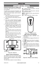
Page 19: ...slide switch on the receiver can be used to operate the heater Note When batteries are replaced the learning process above must be repeated LEARN REMOTE OFF ON Figure 20 Receiver Slide Switch Learn Button Key Settings ON Operates unit to on position manually operated solenoid ON OFF Operates unit to off position manually operated solenoid OFF MODE Changes unit from manual mode to thermo mode SET S...

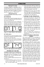
Page 20: ...reen will display the set temperature for 3 sec onds then flash the set temperature for 3 seconds then LCD screen will default to display the room temperature To Change The Set Temperature 1 Press and hold the SET key until the desired set temperature is reached The LCD screen set numbers will increase from 45 to 99 then restart over at 45 2 Release the SET key The LCD screen will display the set ...

Page 21: ...ow in structions at bottom of this page Notice Do not mistake orange flames with yellow tipping Dirt or other fine particles enter the heater and burn causing brief patches of orange flame Approx 3 6 Above Top of Logs More Than 8 Above Top of Logs Approx 3 6 Above Top of Logs More Than 8 Above Top of Logs Figure 27 Correct Burner Flame Pattern Figure 28 Incorrect Burner Flame Pattern BURNER FLAME ...

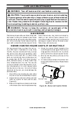
Page 22: ...ir Inlet Holes BURNER INJECTOR HOLDER AND PILOT AIR INLET HOLE We recommend that you clean the unit ev ery 2 500 hours of operation or every three months We also recommend that you keep the burner tube and pilot assembly clean and free of dust and dirt To clean these parts we recommend using compressed air no greater than 30 PSl Your local computer store hardware store or home center may carry com...

Page 23: ...u may blow through a drinking straw if compressed air is not available CARE AND MAINTENANCE ODS PILOT CABINET Air Passageways Use a vacuum cleaner or pressurized air to clean Exterior Use a soft cloth dampened with a mild soap and water mixture Wipe the cabinet to remove dust LOGS If you remove logs for cleaning refer to Installing Logs page 16 to properly replace logs Replace log s if broken or c...

Page 24: ...et pressure exceeds 9 5 WC This is to prevent the operation of the unit on the wrong gas propane LP If your natural gas supply exceeds 9 5 WC the unit will not operate Either contact your gas supplier to check and adjust the inlet pressure or a qualified service technician can bypass the pressure switch Before attempting to bypass the pressure switch make sure the type of gas being used is correct...

Page 25: ...ontrol knob while pressing ignitor button 3 Continue holding down con trol knob Repeat igniting op eration until air is removed 4 Clean ODS pilot see Care and Maintenance page 22 or replace ODS pilot assembly 5 Check inlet gas pressure or replace inlet gas regulator 6 Turn control knob to PILOT position 7 Contact local propane LP gas company ODS pilotlightsbutflame goes out when control knob is re...

Page 26: ...ontact local gas supplier Gas odor during com bustion 1 Foreign matter between control valve and burner 2 Gas leak See Warning Statement at top of page 24 1 Take apart gas tubing and remove foreign matter 2 Locate and correct all leaks see Checking Gas Connec tions page 14 Slight smoke or odor during initial operation 1 Residues from manufactur ing process 1 Problem will stop after a few hours of ...

Page 27: ... odor causing products while heater is running 2 Locate and correct all leaks see Checking Gas Connec tions page 14 3 Refill supply tank Propane LP models Heater shuts off in use ODS operates 1 Not enough fresh air is avail able 2 Low line pressure 3 ODS pilot is partially clogged 1 Open window and or door for ventilation 2 Contact local gas supplier 3 Clean ODS pilot see Care and Maintenance page...

Page 28: ...www usaprocom com 200204 01B 28 REM OTE OFF ON LEA RN TE MP 6 7 9 10 11 5 8 1 2 3 16 13 14 12 15 4 PARTS MODEL QNSD250RT ...

Page 29: ...wer Bracket 2 3 QDB29100B Screen 1 4 161139 01 ODS Pilot 1 5 161338 01 Ignitor 1 6 Regulator 1 7 MRT 01 Control Valve 1 8 QB46000C R Leg Assembly Right Side 1 9 QB46000C L Leg Assembly Left Side 1 10 RG04 1M Receiver Box 1 11 RG04 1T Remote Control 1 FB28D500 B Log Set 1 12 FB28D501 B Log 1 1 13 FB28D502 B Log 2 1 14 FB28D503 B Log 3 1 15 FB28D504 B Log 4 1 16 FB28D505 B Log 5 1 Parts Available No...

Page 30: ...s malfunctioning Type of gas used Propane LP or Natural gas NG Purchase date Usually we will ask you to return the defec tive part to the factory PARTS NOT UNDER WARRANTY Contact authorized dealers of this product If they can t supply original replacement part s call Customer Service toll free at 1 866 573 0674 for referral information When calling Customer Service have ready Model number of your ...

Page 31: ...ied heat propane LP gas supply might be low propane LP units only You may feel your gas pressure is too low If so contact your local gas supplier TECHNICAL SERVICE You may have further questions about installation operation or troubleshooting If so contact ProCom Heating Inc at 1 866 573 0674 When calling please have your model and serial numbers of your heater ready ...

Page 32: ...ng condition Warranty part s MUST be obtained through ProCom Heating Inc who will provide original factory replacement parts Failure to use original factory replacement parts voids this warranty IMPORTANT The heater MUST be installed by a qualified installer in accordance with all local codes and instructions furnished with the unit or the warranty is voided WHAT IS NOT COVERED This warranty does ...

Reviews: