Page 4 | 49
16.2 Disposal of the Dumo ............................................................................................................................ 49
17
Notes ......................................................................................................................................................... 49
18
Acknowledgements ................................................................................................................................... 49
List of Figures and Tables
Figure 1 Dumo structure and main parts ................................................................................................................ 9
Figure 2 Dumo main dimensions ........................................................................................................................... 12
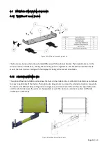
Figure 3 Wall/Din-rail mounting bracket ............................................................................................................... 13
Figure 4 Adjustable installation arm ...................................................................................................................... 13
Figure 5 Inductive Electrification Technology ....................................................................................................... 14
Figure 6: Illustration of un-calibrated measuring behavior .................................................................................. 15
Figure 7: Effect of Ambient Temperature............................................................................................................. 16
Figure 8: Installation height ................................................................................................................................... 17
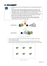
Figure 9: Installation Point in terms of air flow .................................................................................................... 18
Figure 10: Installation Grid .................................................................................................................................... 18
Figure 11: Connecting power input ...................................................................................................................... 20
Figure 12: Connecting Relays ................................................................................................................................ 21
Figure 13: mA loop connection............................................................................................................................. 22
Figure 14: RS485 connections............................................................................................................................... 23
Figure 15: Connecting a RS485 Network .............................................................................................................. 24
Figure 16: Settings after Auto setup ..................................................................................................................... 27
Figure 17: Front view of display............................................................................................................................ 28
Figure 18: Bottom view of buttons ....................................................................................................................... 28
Figure 19: Example for display calibration ........................................................................................................... 33
Figure 20: DustTool main window ........................................................................................................................ 36
Figure 21: Sintrol Network Example ..................................................................................................................... 38
Figure 22 Remove bolts at the front cover ............................................................................................................ 40
Figure 23: Cleaning the probe ............................................................................................................................... 40
Figure 24: Removing the rear cover ..................................................................................................................... 41
Figure 25: Replacing the fan ................................................................................................................................. 41
Table 1: Relay functional logic ............................................................................................................................... 25
Table 2 LED and Display functional logic ............................................................................................................... 26
Table 3 Selectable mode parameters .................................................................................................................... 29
Table 4: Parameter table ....................................................................................................................................... 30
Table 5: Technical specifications .......................................................................................................................... 43
Summary of Contents for Sintrol Dumo
Page 45: ...Page 45 49 15 Appendix 15 1 ISO 9001 certificate ...
Page 46: ...Page 46 49 15 2 MODBUS RTU register map ...
Page 47: ...Page 47 49 ...
Page 48: ...Page 48 49 ...


