background image

Prodigy

r

 Manual Powder Spray Gun

8

Part 1053680E05

E

 2007 Nordson Corporation

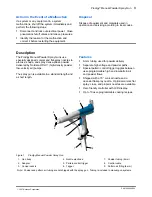
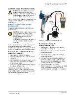
Nozzle Disassembly and Cleaning 

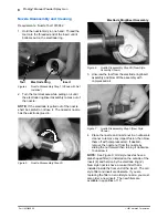
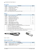
Requirements:  Nozzle Tool 1073682

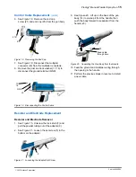
1. Hold the nozzle firmly in one hand.  Thread the

tool onto the threaded end of the insert until it
bottoms out on the electrode ring.

Insert

Electrode Ring

Tool

Figure 4

Nozzle Disassembly Step 1 (Shown with Nut
Installed)

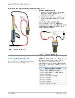
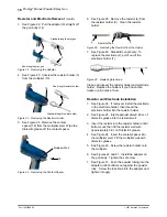
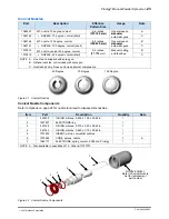
2. Turn the tool clockwise while pulling on it until

the electrode ring/insert assembly comes out of
the nozzle.

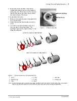
NOTE:  If the electrode is pulled out of the nozzle
shell, be careful to not lose it.  The dual slot nozzle
has the electrode glued in.

Figure 5

Nozzle Disassembly Step 2A

Electrode Ring/Insert Assembly
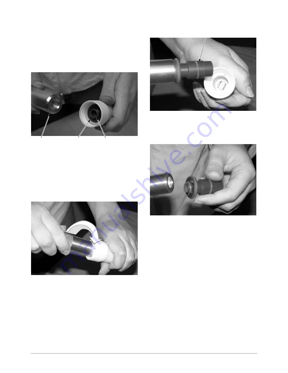
Figure 6

Nozzle Disassembly Step 2B (New Style
Assembly Shown)

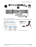
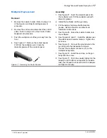
3. Unscrew the tool from the electrode ring/insert

assembly and blow off the assembly with
compressed air.

Figure 7

Nozzle Disassembly Step 3 (New Style
Shown)

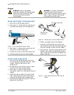
4. Place the nozzle and nozzle nut in an ultrasonic

cleaner to remove any impact fusion, then blow
them off with compressed air.  If desired,
remove the nozzle nut from the nozzle by
sliding the nut forward then turning it clockwise
to unscrew it.

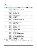
NOTE:  See Figure 9.  Old style nozzles have a
disk-shaped filter (3) installed on the outside of the
insert (6) and held on by the electrode ring (2).
New style nozzles have a conical filter that is
installed inside the front end of the insert.  The old
style filter and insert are obsolete.  if you are
replacing the filter on an old style nozzle, you must
also order a new insert.  The new filters are
available in quantities of 10.

Summary of Contents for Powder Spray Gun

Page 1: ...l Part 1053680E05 Issued 6 07 NORDSON CORPORATION AMHERST OHIO USA For parts and technical support call the Finishing Customer Support Center at 800 433 9319 This document is available on the Internet...

Page 2: ...trode Installation 16 Multiplier Replacement 17 Removal 17 Assembly 17 Parts 18 Prodigy Manual Spray Gun Standard Length 18 Prodigy Manual Spray Gun Short Length 20 Service Kits 22 Options 22 Powder a...

Page 3: ...pprovals Make sure all equipment is rated and approved for the environment in which it is used Any approvals obtained for Nordson equipment will be voided if instructions for installation operation an...

Page 4: ...ohm as measured with an instrument that applies at least 500 volts to the circuit being evaluated S Equipment to be grounded includes but is not limited to the floor of the spray area operator platfor...

Page 5: ...y Nordson HDLVr high density powder low velocity air pumps The spray gun is available in a standard length and a short length Features S 8 mm tubing used for powder delivery S Separate high voltage an...

Page 6: ...3 Spring plunger 4 Electrode 5 Electrode holder 6 Resistor 7 Resistor holder 8 Contact spacer 9 Voltage multiplier 10 Ground stud 11 Cable multiplier connection 12 6 mm tube fitting pattern air 13 Co...

Page 7: ...dson Corporation PRODIGY NORDSON CORPORATION SIRA05ATEX5212X EEx 2mJ 1180 II 2D 23 22 7 6 8 10 15 21 18 12 17 16 13 14 19 20 18 14 24 11 9 1 2 in 19 1 2 3 Figure 3 Short Length Spray Gun Section View...

Page 8: ...safety instructions in this document and all other related documentation WARNING Installation in Europe shall carried out by suitably trained personnel in accordance with the applicable code of pract...

Page 9: ...e LED on the end plate lights when the spray trigger is pulled and high voltage is generated Pattern Control Trigger The pattern control trigger toggles between the preset settings High mode and the L...

Page 10: ...ure 6 Nozzle Disassembly Step 2B New Style Assembly Shown 3 Unscrew the tool from the electrode ring insert assembly and blow off the assembly with compressed air Figure 7 Nozzle Disassembly Step 3 Ne...

Page 11: ...t 3 Turn the tool counterclockwise to remove it from the insert Check the nozzle The electrode ring should be approximately 1 4 inch inside the nozzle lip Electrode Ring Nozzle Lip Figure 8 Nozzle Re...

Page 12: ...conveyor chain rollers and part hangers for powder buildup The resistance between the parts and ground must be 1 megohm or less For best results 500 ohms or less is recommended Poor connection in hig...

Page 13: ...ance Test Control Cable End to Adapter Spring Plunger 1 See Figure 10 Remove the nozzle 2 Disconnect the control cable from the manual control unit 3 Short together cable connector pins J1 2 J1 3 and...

Page 14: ...multiplier resistor resistance check was out of range replace the multiplier 153 187 megohms Figure 12 Resistor Resistance Test Control Cable Continuity Tests Make continuity tests with a standard oh...

Page 15: ...SPRAY TRIGGER COMMON PATTERN TRIGGER Figure 13 Control Cable Continuity Tests Trigger Switch Continuity Test Disconnect the control cable from the trigger switch as described in Cable Replacement on p...

Page 16: ...dard gun powder tube Figure 16 Removing the Air Cap and Powder Tube 6 Slide a new powder tube into the adapter 7 Screw the nozzle back into the retaining nut then install the nozzle onto the powder tu...

Page 17: ...Cable 9 See Figure 20 Lift up on the back of the gun body 14 to unsnap it from the handle then push the body forward to separate it from the handle 23 Feed cable through here 14 23 Figure 20 Separati...

Page 18: ...lectrode 2 pull it out of the electrode holder 1 2 1 Figure 26 Replacing Electrode Clean and inspect the resistor holder and electrode holder Replace the holders If you find carbon tracks or pin holes...

Page 19: ...spacer into the multiplier well Fill the multiplier well with dielectric grease 2 Install the multiplier into the gun body 3 Fill the resistor holder well with dielectric grease Refer to Resistor and...

Page 20: ...9 288552 S POWER SUPPLY 95 kV negative 1 C 20 S CAP end handgun 1 21 982800 S SCREW pan recessed M4 x 6 black zinc 1 22 1069680 S GASKET cover handgun 1 23 288561 S HANDLE w cover handgun 1 23A 288534...

Page 21: ...er Spray Gun 19 Part 1053680E05 E 2007 Nordson Corporation 1 2 3 4 14 13 12 11 10 9 5 8 7 6 23 22 21 19 18 17 16 15 20 30 24 25 27 26 28 29 31 32 34 33 32 35 36 23A 8 37 Figure 28 Prodigy Manual Spray...

Page 22: ...tive 1 C 20 S CAP end handgun 1 21 982800 S SCREW pan recessed M4 x 6 black zinc 1 22 1069680 S GASKET cover handgun 1 23 288561 S HANDLE w cover handgun 1 23A 288534 S S GASKET base hand gun 1 24 288...

Page 23: ...owder Spray Gun 21 Part 1053680E05 E 2007 Nordson Corporation 3 4 14 13 12 11 10 9 5 8 7 6 23 22 21 19 18 17 16 15 20 30 24 25 27 26 28 29 31 32 34 33 32 35 36 23A 8 37 Figure 29 Prodigy Manual Spray...

Page 24: ...BLE handgun 4 meter extension E 1067602 LANCE EXTENSION 150 mm Prodigy F G 1067643 LANCE EXTENSION 300 mm Prodigy F G NOTE A For operators with larger hands Replaces standard pad B Order the appropria...

Page 25: ...NOTE A One of each supplied with spray gun B Optional nozzles not included with spray gun C Nozzle shell only Does not include internal components 40 Degree 70 Degree 100 Degree Figure 31 Conical Nozz...

Page 26: ...guns C 1077392 KIT nozzle flat spray Prodigy 140 degree 11 13 inches 279 330 Large flat f A 1077397 S NOZZLE shell with electrode flat spray Prodigy 140 degree 279 330 mm g surfaces C 1073911 KIT nozz...

Page 27: ...ozzles Item Part Description Quantity Note S NOZZLE ASSEMBLIES 1 A 1 940203 S O RING silicone 0 875 x 1 00 x 0 063 in 1 2 1047537 S ELECTRODE ring 1 3 940126 S O RING silicone 0 375 x 0 50 x 0 063 in...

Page 28: ...Prodigyr Manual Powder Spray Gun 26 Part 1053680E05 E 2007 Nordson Corporation...

Page 29: ...EEC ATEX Directive 94 9 EC The conformity is under observance of the following standards or standards documents EN292 EN50014 EN50081 1 EN1953 EN50050 EN50082 2 IEC 417L EN60204 EN50281 1 1 FM7260 EN...

Page 30: ......

Reviews: