Prodigy
r
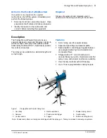
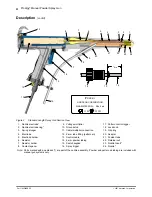
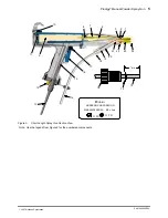
Manual Powder Spray Gun
11
Part 1053680E05
E
2007 Nordson Corporation
Continuity and Resistance Tests
WARNING: Turn off the electrostatic
voltage and ground the spray gun
electrode before performing the following
tasks. Failure to observe this warning
could result in a severe shock.
Use the following tests to isolate problems with the
voltage multiplier or resistor, control cable, and
trigger switch.
Multiplier and Resistor Assembly
Resistance Test
Resistance tests must be made with a 500 volt
megohm meter.
CAUTION: Short together the three pins
in the multiplier receptacle, or the
designated pins in the control cable,
before testing the continuity and
resistance of the
multiplier/resistor/electrode assembly. If
not shorted, the multiplier could be
damaged.
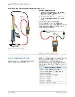
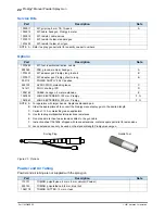
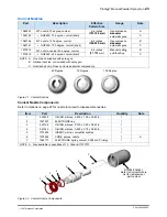
Use the optional shorting plug shown in Figure 11
when testing resistance from the multiplier
receptacle to the adapter spring plunger. Refer to
Options in Parts for the shorting plug part number.
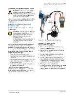
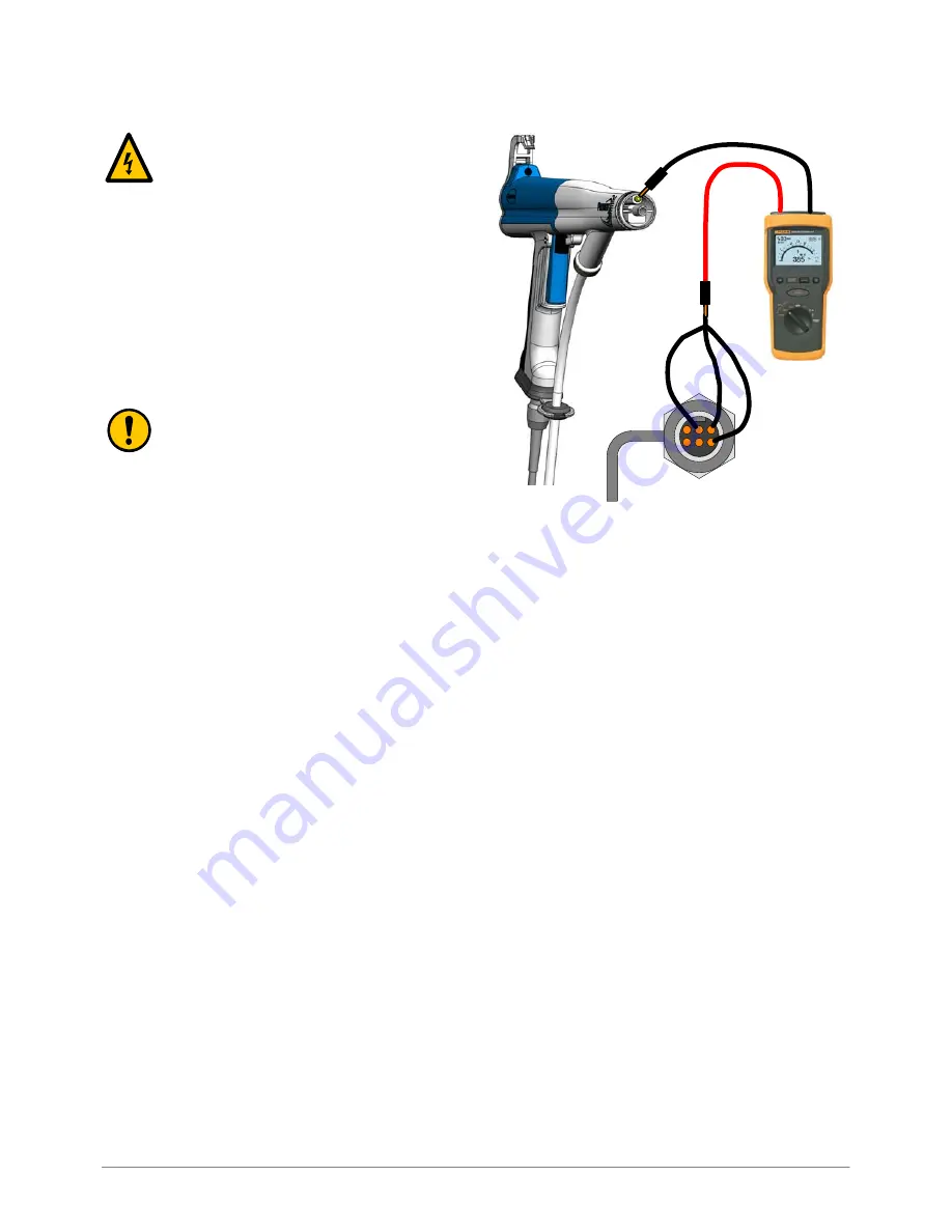
Resistance Test - Control Cable End to
Adapter Spring Plunger
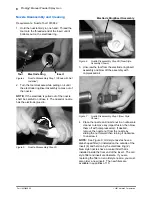
1. See Figure 10. Remove the nozzle.
2. Disconnect the control cable from the manual
control unit.
3. Short together cable connector pins J1-2, J1-3,
and J1-4 and connect them to the positive
megohm meter probe.
4. Connect the negative megohm meter probe to
the adapter spring plunger.
The megohm meter reading should be
350-420 megohms. If the reading is out of this
range, test the resistor separately. If the resistor
passes the test, replace the multiplier.
Pin 2
Pin 3
Pin 4
350-420
megohms
Figure 10
Cable End to Spring Plunger Test
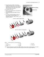
Resistance Test Using the
Optional Shorting Plug
1. See Figure 11. Remove the end cap and
nozzle from the spray gun.
2. Disconnect the multiplier connector from the
multiplier receptacle.
3. Connect the shorting plug connector to the
multiplier receptacle.
4. Connect the megohm meter positive probe to
the shorting plug ring-tong terminal and the
negative probe to the spring plunger. (If the
reading is infinite, switch the probes).
5. The megohm meter should read
350-420 megohms. If the reading is out of this
range, test the resistor separately. If the
resistor passes the test, replace the multiplier.


