background image


15


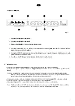
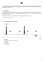
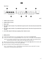
Rear Panel: 


pict.2 


1.  Antenna A input connector 


2.  Antenna B input connector 


3. Mains 

socket 


4.  TNC female output connectors. They distribute the signal received to the antenna B input sockets of the 

receivers. 


5.  TNC female output connectors. They distribute the signal received to the antenna A input sockets of the 

receivers. 


6.  Four 12VCD outputs for direct power supplying of the 4 wireless receivers 


4. INSTALLATION 


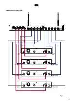
Connect the two antennas of one of 4 connected receivers  to the 2 inputs A and B 

(pict.2 ref.1,2)


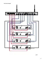
Connect the antenna A and B inputs 

(pict.2 rif.4,5)

 of the receivers to the A and B outputs of the splitter 

(pict.3)


Note:To ensure optimum performance of the unit, keep it away from humidity or water. This antenna booster kit  

provides enhanced S/N ratio for better reception and longer distance transmission. 


After connecting the antennas, connect the AC/DC adapter to the UHF Splitter 

(fig.2 rif.3)

 and to the mains outlet. 


Connect receivers' input supply to 12Vdc outputs 

( pict.2 ref.3)


Switch the unit ON, the Power LED will light up and the unit is ready for use. 


Note:  For short distances (10/15 mt.) a 50

 RG58-type coaxial cable can be used, while RG213U or higher 

feature cables are recommended for longer distances.


Summary of Contents for UHFSPLITAL

Page 1: ...MANUALE UTENTE INSTRUCTION MANUAL Ripartitore quadruplo di antenne 4 way Antenna Splitter UHFSPLITAL...

Page 2: ...2...

Page 3: ...3 INDICE 1 PRECAUZIONI D USO 4 2 DESCRIZIONE 6 3 FUNZIONI E CONTROLLI 6 4 INSTALLAZIONE 7 5 CONTENUTO DELLA CONFEZIONE 9 6 CARATTERISTICHE TECNICHE 9...

Page 4: ...e non interferisca con l adeguata ventilazione Per esempio l apparecchio non deve essere collocato su un letto copri divano o superfici simili che possono bloccare le aperture di ventilazione o posto...

Page 5: ...o al di l di quanto descritto nelle istruzioni di funzionamento Ogni altra riparazione deve essere affidata a personale specializzato IMPORTANTI NORME DI SICUREZZA Installare seguendo le istruzioni Il...

Page 6: ...fessionale attivo permette la distribuzione su quattro canali diversity del segnale ricevuto dalle due antenne principali master In abbinamento con 2 antenne e a quattro ricevitori multifrequenza si r...

Page 7: ...rif 4 5 dei ricevitori con le uscite A e B del ripartitore splitter fig 3 Nota Per la miglior funzionalit del prodotto consigliabile l installazione in posizione riparata dall umidit o dall acqua dir...

Page 8: ...8 Diagramma di connessione fig 3...

Page 9: ...and UHF 600 740MHz For receiver type UHF Synthesized Gain 3 dB Impedance 50 T H D 0 8 Pnom 1KHz S N Ratio 90dB Dynamic 100dB RF sensitivity 100dBm 30dB SINAD Power Supply 110 230V 50 60Hz 12Vdc adapte...

Page 10: ...10...

Page 11: ...11 INDEX 1 IMPORTANT SAFETY INSTRUCTIONS 12 2 DESCRIPTION 14 4 INSTALLATION 15 5 PACKAGE CONTENT 17 6 TECHNICAL FEATURES 17...

Page 12: ...TIONS Water and moisture This apparatus should not be used near water i e bathtub kitchen sink swimming pools etc Ventilation This apparatus should be placed in a position that does not interfere with...

Page 13: ...ange in performance If the product has been dropped or has been damaged in any way Maintenance The user should not attempt any maintenance procedures not described in this user s manual All maintenanc...

Page 14: ...ve antenna splitter booster splits the signal received from the two main master antennas to four diversity channels Combined with two antennas and four multi frequency receivers it forms a high sensit...

Page 15: ...2 Connect the antenna A and B inputs pict 2 rif 4 5 of the receivers to the A and B outputs of the splitter pict 3 Note To ensure optimum performance of the unit keep it away from humidity or water T...

Page 16: ...16 Connection diagram pict 3...

Page 17: ...nd UHF 600 740MHz For receiver type UHF Synthesized Gain 3 dB Impedance 50 T H D 0 8 Pnom 1KHz S N Ratio 90dB Dynamic 100dB RF sensitivity 100dBm 30dB SINAD Power Supply 230Vac 50 60Hz 12Vdc adapter D...

Page 18: ...18...

Page 19: ...19...

Page 20: ...20 PROEL S p A World Headquarters Factory Via alla Ruenia 37 43 64027 Sant Omero Te Italy Tel 39 0861 81241 Fax 39 0861 887862 E mail info proel com www proel com...

Reviews: