background image

4

General Specifications

„

Electrical Specifications

„

Environmental Specifications

„

Structural Specifications

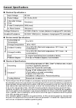
Po

wer Supp

ly

Input Voltage

DC24V

Rated Voltage

DC19.2 to 28.8V

Allowable Voltage 
Drop

5ms (max.)

Power Consumption 26W (max.)

In-Rush Current

30A (max.)

Voltage Endurance

AC1000V 20mA for 1 minute (between charging and FG terminals)

Insulation Resistance

DC500V 10M

 (min.)  (between charging and FG terminals)

Phy

s

ic

al

Surrounding Air 
Temperature

0 to 50

°

C

Storage Temperature

-20 to +60

°

C

Ambient Humidity

10 to 90% RH (Wet bulb temperature: 39°C max. - no 
condensation.)

Storage Humidity

10 to 90% RH (Wet bulb temperature: 39°C max. - no 
condensation.)

Dust

0.1mg/m

3

 and below (non-conductive levels)

Pollution Degree

For use in Pollution Degree 2 environment.

Ins

tal

lation

Grounding

Grounding resistance of 100

Ω, 

2mm

2

 or thicker wire, or your 

country’s applicable standard.
(Same for FG and SG terminals)

Structure

*1

*1 The front face of the GP unit, installed in a solid panel, has been tested using conditions equivalent to 

the standards shown in the specification. Even though the GP unit’s level of resistance is equivalent to 
these standards, oils that should have no effect on the GP can possibly harm the unit. This can occur in 
areas where either vaporized oils are present, or where low viscosity cutting oils are allowed to adhere 
to the unit for long periods of time. If the GP’s front face protection sheet becomes peeled off, these 
conditions can lead to the ingress of oil into the GP and separate protection measures are suggested.


Also, if non-approved oils are present, it may cause deformation or corrosion of the front panel’s plastic 
cover. Therefore, prior to installing the GP be sure to confirm the type of conditions that will be present 
in the GP’s operating environment.


If the installation gasket is used for a long period of time, or if the unit and its gasket are removed from 
the panel, the original level of the protection cannot be guaranteed. To maintain the original protection 
level, be sure to replace the installation gasket regularly.

Rating: IP65f  NEMA #250 TYPE 1
(Front surface at panel embedding)
Feature size: All-in-one
Installation configuration: Panel embedding

Cooling Method

Natural air circulation

Summary of Contents for AGP3300-U1-D24

Page 1: ...th special attention to quality However should you find anything damaged or missing please contact your local GP distributor immediately About the Manual For detailed information on the GP3000 series...

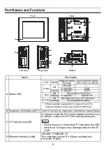
Page 2: ...Card D Ethernet Interface LAN 10BASE T 100BASE TX This interface uses an RJ 45 type modular jack connector 8 pins A Front D F G E H B C I J Rear Right side Left side Bottom Color Indicator Operation...

Page 3: ...oltage DC5V 5 Output current 500mA max The maximum communication distance 5m G Serial Interface COM1 D sub 9 pin plug type RS232C RS422 and RS485 are switched by software H Serial Interface COM2 D sub...

Page 4: ...standards shown in the specification Even though the GP unit s level of resistance is equivalent to these standards oils that should have no effect on the GP can possibly harm the unit This can occur...

Page 5: ...in RS232C RS422 RS485 Signal Name Meaning Signal Name Meaning 1 CD Carrier Detect RDA Receive Data A 2 RD RXD Receive Data RDB Receive Data B 3 SD TXD Send Data SDA Send Data A 4 ER DTR Data Terminal...

Page 6: ...RON Corp Fitting fastener 4 40 UNC Pin RS422 RS485 Signal Name Meaning 1 TRMRX Termination Receiver side 100 2 RDA Receive Data A 3 SDA Send Data A 4 RS RTS Request for Send 5 SG Signal Ground 6 VCC 5...

Page 7: ...he GP to exceed its standard operating temperature 2 GP Installation 1 Create a Panel Cut and insert the GP into the panel from the front Deter mine the panel thickness according to the panel thicknes...

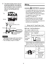
Page 8: ...other power level can damage both the GP and the power supply When the FG terminal is connected be sure the wire is grounded 1 Wiring the DC Type Power Cord Power Cord Specifications Use copper condu...

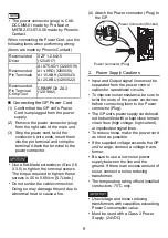
Page 9: ...s must be separated from the power control cables for operational circuits To improve noise resistance be sure to twist the ends of the power cord wires before connecting them to the Power connector P...

Page 10: ...mm2 Create the connection point as close to the GP unit as possible and make the wire as short as possible When using a long grounding wire replace the thin wire with a thicker wire and place it in a...

Page 11: ...t The GP unit s rear face is not approved as an enclosure When building the GP unit into an end use product be sure to use an enclosure that satisfies standards as the end use product s overall enclos...

Page 12: ...in this document is subject to change without notice Copyright 2009 Digital Electronics Corporation All rights reserved PFX119872F AGP3300 U1 MT02E BTH 2010 6 SS B Inquiry Do you have any questions a...

Reviews: