background image

9

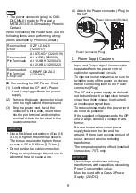
• The power connector (plug) is CA5-

DCCNM-01 made by Pro-face or 
MSTB2,5/3-ST-5,08 made by Phoenix 
Contact.

When connecting the Power Cord, use the 
following items when performing wiring: 
(Items are made by Phoenix Contact.)

„

Connecting the GP Power Cord

(1) Confirm that the GP unit’s Power 

Cord is unplugged from the power 
supply.

(2) Remove the power connector (plug) 

from the right side of the main unit.

(3) Strip the power cord, twist the 

conductor’s wire ends, insert them 
into the pin terminal and crimp the 
terminal. Attach the terminal to the 
power connector.

• Use a flat-blade screwdriver (Size 0.6 

X 3.5) to tighten the terminal screws.


The torque required to tighten these 
screws is 0.5 to 0.6N

m [5-7Lb

In.].

• Do not solder the cable connection.


Doing so may damage the unit due to 
abnormal heat or cause a fire. 

(4) Attach the Power connector (Plug) to 

the GP.

2.

Power Supply Cautions

• Input and Output signal lines must be 

separated from the power control 
cables for operational circuits.

• To improve noise resistance, be sure to 

twist the ends of the power cord wires 
before connecting them to the Power 
connector (Plug).

• The GP unit’s power supply cord should 

not be bundled with or kept close to main 
circuit lines (high voltage, high current), 
or input/output signal lines.

• To reduce noise, make the power cord 

as short as possible.

• If the supplied voltage exceeds the GP 

unit’s range, connect a voltage trans-
former.

• Be sure to use a low noise power 

supply between the line and the 
ground. If there is an excess amount of 
noise, connect a noise reducing 
transformer.

• The temperature rating of field installed 

conductors: 75

o

C only.

• Use voltage and noise reducing 

transformers with capacities exceeding 
Power Consumption value.

• Must be used with a Class 2 Power 

Supply. (24VDC)

Recomended 
Driver

SZF 1-0.6x3.5 
(1204517)

Recomended 
Pin Terminals

AI 0.75-8GY (3200519)
AI 1-8RD (3200030)
AI 1.5-8BK (3200043)
AI 2.5-8BU (3200522)

Recomended 
Pin Terminal 
Crimp Tool

CRIMPFOX ZA 3 
(1201882)

Power Connector (Socket)

Power connector (Plug)

FG

+

-

Summary of Contents for AGP3300-U1-D24

Page 1: ...th special attention to quality However should you find anything damaged or missing please contact your local GP distributor immediately About the Manual For detailed information on the GP3000 series...

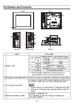
Page 2: ...Card D Ethernet Interface LAN 10BASE T 100BASE TX This interface uses an RJ 45 type modular jack connector 8 pins A Front D F G E H B C I J Rear Right side Left side Bottom Color Indicator Operation...

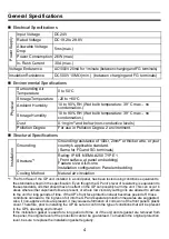
Page 3: ...oltage DC5V 5 Output current 500mA max The maximum communication distance 5m G Serial Interface COM1 D sub 9 pin plug type RS232C RS422 and RS485 are switched by software H Serial Interface COM2 D sub...

Page 4: ...standards shown in the specification Even though the GP unit s level of resistance is equivalent to these standards oils that should have no effect on the GP can possibly harm the unit This can occur...

Page 5: ...in RS232C RS422 RS485 Signal Name Meaning Signal Name Meaning 1 CD Carrier Detect RDA Receive Data A 2 RD RXD Receive Data RDB Receive Data B 3 SD TXD Send Data SDA Send Data A 4 ER DTR Data Terminal...

Page 6: ...RON Corp Fitting fastener 4 40 UNC Pin RS422 RS485 Signal Name Meaning 1 TRMRX Termination Receiver side 100 2 RDA Receive Data A 3 SDA Send Data A 4 RS RTS Request for Send 5 SG Signal Ground 6 VCC 5...

Page 7: ...he GP to exceed its standard operating temperature 2 GP Installation 1 Create a Panel Cut and insert the GP into the panel from the front Deter mine the panel thickness according to the panel thicknes...

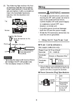
Page 8: ...other power level can damage both the GP and the power supply When the FG terminal is connected be sure the wire is grounded 1 Wiring the DC Type Power Cord Power Cord Specifications Use copper condu...

Page 9: ...s must be separated from the power control cables for operational circuits To improve noise resistance be sure to twist the ends of the power cord wires before connecting them to the Power connector P...

Page 10: ...mm2 Create the connection point as close to the GP unit as possible and make the wire as short as possible When using a long grounding wire replace the thin wire with a thicker wire and place it in a...

Page 11: ...t The GP unit s rear face is not approved as an enclosure When building the GP unit into an end use product be sure to use an enclosure that satisfies standards as the end use product s overall enclos...

Page 12: ...in this document is subject to change without notice Copyright 2009 Digital Electronics Corporation All rights reserved PFX119872F AGP3300 U1 MT02E BTH 2010 6 SS B Inquiry Do you have any questions a...

Reviews: