background image

63

Notes

VEGASON 62 • Profibus PA

28785-EN-150603

Summary of Contents for VEGASON 62

Page 1: ...Operating Instructions Ultrasonic sensor for continuous level measurement VEGASON 62 Profibus PA Document ID 28785 ...

Page 2: ...ower supply 5 1 Preparing the connection 20 5 2 Connection procedure 21 5 3 Wiring plan single chamber housing 22 5 4 Wiring plan double chamber housing 23 5 5 Wiring plan version IP 66 IP 68 1 bar 25 5 6 Switch on phase 26 6 Set up with the display and adjustment module PLICSCOM 6 1 Insert display and adjustment module 27 6 2 Adjustment system 28 6 3 Setup steps 29 6 4 Menu schematic 39 6 9 Savin...

Page 3: ...0 1 Technical data 50 10 2 Profibus PA 54 10 3 Dimensions 58 Safety instructions for Ex areas Take note of the Ex specific safety instructions for Ex applications These instructions are attached as documents to each instrument with Ex approval and are part of the operating instructions manual Editing status 2015 05 21 ...

Page 4: ...s symbol indicates helpful additional information Caution If this warning is ignored faults or malfunctions can result Warning If this warning is ignored injury to persons and or serious damage to the instrument can result Danger If this warning is ignored serious injury to persons and or destruction of the instrument can result Ex applications This symbol indicates special instructions for Ex app...

Page 5: ...iate or incorrect use of the instrument can give rise to application specific hazards e g vessel overfill or damage to system components through incorrect mounting or adjustment 2 4 General safety instructions This is a state of the art instrument complying with all prevailing regulations and guidelines The instrument must only be operated in a technically flawless and reliable condition The opera...

Page 6: ...andard in field instrumentation The device fulfills the requirements of the following NAMUR recom mendations NE 21 Electromagnetic compatibility of equipment NE 43 Signal level for malfunction information from measuring transducers NE 53 Compatibility of field devices and display adjustment components For further information see www namur de 2 8 Environmental instructions Protection of the environ...

Page 7: ...tive scope of delivery results from the order specification The VEGASON 62 consists of the components Process fitting with transducer Housing with electronics optionally available with plug connector Housing cover optionally available with display and adjustment module PLICSCOM The components are available in different versions 1 2 3 Fig 1 VEGASON 62 threaded version with plastic housing 1 Housing...

Page 8: ...an appropriate output signal and outputted as measured value Power supply via the Profibus DP PA segment coupler or VEGALOG 571 EP cards A two wire cable according to Profibus specification serves as carrier of both power and digital data transmission for multiple sensors The instrument profile of VEGASON 62 corresponds to profile specification version 3 0 The backlight of the display and adjustme...

Page 9: ... the orientation and storage markings on the outside Unless otherwise indicated the packages must be stored only under the following conditions Not in the open Dry and dust free Not exposed to corrosive media Protected against solar radiation Avoiding mechanical shock and vibration Storage and transport temperature see chapter Supplement Technical data Ambient conditions Relative humidity 20 85 3 ...

Page 10: ...the supplementary instructions manual Protective cover Document ID 34296 Flanges are available in different versions according to the following standards DIN 2501 EN 1092 1 ANSI B 16 5 JIS B 2210 1984 GOST 12821 80 You can find additional information in the supplementary instructions manual Flanges according to DIN EN ASME JIS Document ID 31088 Electronics module VEGASON series 60 is a replacement...

Page 11: ...t additional protection against moisture penetration by leading the connection cable downward in front of the cable entry Rain and condensation water can thus drain off This ap plies mainly to outdoor mounting as well as installation in areas where high humidity is expected e g through cleaning processes or on cooled or heated vessels Fig 2 Measures against moisture ingress In the case of instrume...

Page 12: ...ng distance 1 full 2 empty max measuring distance 3 Measuring range Gauge pressure in the vessel does not influence VEGASON 62 Low pressure or vacuum does however damp the ultrasonic pulses This influences the measuring result particularly if the level is very low With pressures under 0 2 bar 20 kPa you should use a different measuring principle e g radar or guided microwave 4 2 Mounting instructi...

Page 13: ...an appropriate adjustment see chapter Setup 1 2 200 mm Fig 5 Mounting on round vessel tops 1 Reference plane 2 Vessel center or symmetry axis If this distance cannot be maintained a false signal storage should be carried out during setup This applies particularly if buildup on the vessel wall is expected In such cases we recommend repeating the false signal storage at a later date with existing bu...

Page 14: ... in out of the socket ca 10 mm Fig 7 Recommended socket mounting If the reflective properties of the medium are good you can mount VEGASON 62 on sockets which are higher than the length of the transducer You will find recommended values for socket heights in the following illustration The socket end should be smooth and burr free if possible also rounded Carry out a false echo storage Socket ...

Page 15: ... to maximum Such an arrangement is suitable primarily for open vessels such as e g overflow basins 200 4 0 0 x 4 0 0 4 5 Fig 10 Beam deflector The ultrasonic sensor should be installed at a location where no installations cross the ultrasonic beam Vessel installations such as for example ladders limit switches heat ing spirals struts etc can cause false echoes that interfere with the useful echo M...

Page 16: ...void direct false echoes α α α α α α Fig 11 Cover flat large area profiles with deflectors If there are agitators in the vessel a false signal storage should be carried out with the agitators in motion This ensures that the interfer ing reflections from the agitators are saved with the blades in different positions Fig 12 Agitators Do not mount the instruments in or above the filling stream Make s...

Page 17: ...s unaffected by foam generation and is particu larly suitable for such applications If there are strong air currents in the vessel e g due to strong winds in outdoor installations or air turbulence e g by cyclone extraction you should mount VEGASON 62 in a standpipe or use a different measuring principle e g radar or guided radar TDR By using a standpipe surge or bypass tube the influence of vesse...

Page 18: ...amples give you introductory information on the flow measurement Detailed planning information is available from flume manufacturers and in special literature 3 4 hmax 50 mm 90 2 3 1 h max d min 2 mm x h max 90 4 2 3 Fig 15 Flow measurement with rectangular flume dmin min distance of the sensor see chapter Technical data hmax max filling of the rectangular flume 1 Overflow orifice side view 2 Head...

Page 19: ...vel 2 3 4 x hmax 90 hmax d B 1 Fig 16 Flow measurement with Khafagi Venturi flume d Min distance to sen sor hmax max filling of the flume B tightest constriction in the flume 1 Position sensor 2 Venturi flume In general the following points must be observed Installation of the sensor at the inlet side Installation in the centre of the flume and vertical to the liquid surface Distance to the Ventur...

Page 20: ...ut according to the Profibus specification In particular make sure that the termination of the bus is done with appropriate terminating resistors You can find detailed information of the cable specification installa tion and topology in the Profibus PA User and Installation Guide line on www profibus com On the instrument with cable entry NPT and plastic housing there is a metallic threaded insert...

Page 21: ...f the corresponding installation regulations for Ex applica tions In particular make sure that no potential equalisation currents flow over the cable screen In case of grounding on both sides this can be achieved by the use of a capacitor or a separate potential equalisation 5 2 Connection procedure Proceed as follows 1 Unscrew the housing lid 2 If a display and adjustment module is installed remo...

Page 22: ...f the cable entry gland The seal ring must completely encircle the cable 12 Screw the housing lid back on The electrical connection is finished 5 3 Wiring plan single chamber housing The following illustrations apply to the non Ex as well as to the Ex ia version 5 5 5 5 1 2 4 3 Fig 18 Material versions single chamber housing 1 Plastic 2 Aluminium 3 Stainless steel precision casting 4 Stainless ste...

Page 23: ...ded terminals for connection of the external indication VEGADIS 61 3 Ground terminal for connection of the cable screen 4 Spring loaded terminals for voltage supply I2C Display 1 1 2 5 6 7 8 Fig 20 Wiring plan single chamber housing 1 Voltage supply signal output 5 4 Wiring plan double chamber housing The following illustrations apply to the non Ex as well as to the Ex ia version Electronics and t...

Page 24: ...for VEGADIS 61 optional 3 Housing cover electronics compartment 4 Filter element for air pressure compensation 5 Cable gland 1 3 2 Display 1 2 5 6 7 8 I C Fig 22 Electronics compartment double chamber housing 1 Plug connector for VEGACONNECT I C interface 2 Internal connection cable to the connection compartment 3 Terminals for VEGADIS 81 Housing overview Electronics compartment ...

Page 25: ...nnector for VEGACONNECT I C interface 3 Ground terminal for connection of the cable screen I2C 1 1 2 Fig 24 Wiring plan double chamber housing 1 Voltage supply signal output 5 5 Wiring plan version IP 66 IP 68 1 bar 1 2 Fig 25 Wire assignment connection cable 1 brown and blue to power supply or to the processing system 2 Shielding Terminal compartment Wiring plan Wire assignment con nection cable ...

Page 26: ...s are carried out Internal check of the electronics Indication of the instrument type the firmware as well as the sen sor TAGs sensor designation Status byte goes briefly to fault value Then the current measured value will be displayed and the corre sponding digital output signal will be outputted to the cable 1 Switch on phase 1 The values correspond to the actual measured level as well as to the...

Page 27: ...e electronics you can choose any one of four different posi tions each displaced by 90 3 Press the display and adjustment module onto the electronics and turn it to the right until it snaps in 4 Screw housing lid with inspection window tightly back on Disassembly is carried out in reverse order The display and adjustment module is powered by the sensor an ad ditional connection is not necessary Fi...

Page 28: ... ESC key Interrupt input Jump to next higher menu You adjust the instrument via the four keys of the display and adjust ment module The individual menu items are shown on the LC display You can find the functions of the individual keys in the previous illustration By pushing the and keys once the edited value or the cursor changes by one position By pushing the keys longer than 1 s the change will...

Page 29: ... delivered with address 126 With this address it can at first be connected to an existing bus However the address must be changed This can be done in this menu item Sensor address 126 The sensor measures the distance from the sensor to the product surface For indication of the real level an allocation of the measured distance to the percentage height must be carried out The actual level is then ca...

Page 30: ...ing to the percentage value 5 Save the settings with OK and move to Max adjustment with Proceed as follows Max adjustment 100 00 1 000 m d 2 000 m d 1 Prepare the value for editing with OK and set the cursor to the requested position with Set the requested percentage value with and save with OK The cursor jumps now to the distance value 2 Enter the appropriate distance value in m corresponding to ...

Page 31: ... fluctuations in the measured value display e g caused by an agitated product surface a damping can be set This time can be between 0 and 999 seconds Keep in mind that the reaction time of the entire measurement will then be longer and the sensor will react to measured value changes with a delay In general a period of a few seconds is sufficient to smooth the measured value display Damping 0 s Ent...

Page 32: ... designation for the sensor e g the measurement loop name or the tank or product des ignation In digital systems and in the documentation of larger plants a singular designation should be entered for exact identification of individual measuring points Sensor TAG Sensor With this menu item the Basic adjustment is finished and you can now jump to the main menu with the ESC key Menu section display R...

Page 33: ... the respective process conditions In this menu item the measurement reliability of the level echo is displayed as dB value The measurement reliability equals signal strength minus noise The higher the value the more reliable the measurement With a function ing measurement the values are 10 dB With ultrasonic sensors the Echo curve represents the signal strength of the echoes over the measuring ra...

Page 34: ... curve the following are available X Zoom Resolution 1 minute 1 hour 1 day Stop Start Interrupt a recording or start a new recording Unzoom Reset the resolution to minutes As default setting the recording pattern has 1 minute With the adjust ment software PACTware this pattern can be also set to 1 hour or 1 day Echo curve High sockets or vessel installations such as e g struts or agitators as well...

Page 35: ... signal processing is considerably reduced false reflections by agitators or vessel installations can cause measured value fluctuations A false echo memory is thus recommended Profibus transmits two values cyclically The first value is determined in the menu item Channel The selection of the additional cyclical value is made in the menu item Additional PA value The following values are available w...

Page 36: ...rol system The following simulation variables are available Percent Current Pressure with pressure transmitters Distance with radar and guided microwave With Profibus PA sensors the selection of the simulated value is made via the Channel in the menu Basic adjustments How to start the simulation 1 Push OK 2 Select the requested simulation variable with and confirm with OK 3 Set the requested numer...

Page 37: ...structions manual of the respective sensor Reset Select reset In this menu item you select the internal arithmetic unit of the sensor Unit of measurement m d The sensor is already set to the ordered national language In this menu item you can change the language The following languages are available e g in software version 3 50 Deutsch English Français Espanõl Pycckuu Italiano Netherlands Japanese...

Page 38: ... read out or written Sensor address PIN Copy sensor data Copy sensor data In this menu item the PIN is activated deactivated permanently Entering a 4 digit PIN protects the sensor data against unauthorized access and unintentional modifications If the PIN is activated perma nently it can be deactivated temporarily i e for approx 60 min in any menu item The instrument is delivered with the PIN set ...

Page 39: ...nsor details e g approval process fitting seal measuring cell measuring range electronics housing cable entry plug cable length etc Sensor characteristics Display now 6 4 Menu schematic Information Depending on the version and application the highlighted menu windows may not always be available Basic adjustment Basic adjustment 1 Display Diagnostics Service Info Sensor address 1 1 126 Min adjustme...

Page 40: ... 6 C T min 4 5 C Meas reliability 3 2 36 dB Sensor status OK Curve selection 3 3 Echo curve Echo curve 3 4 Presentation of the echo curve Service Basic adjustment 4 Display Diagnostics Service Info False signal suppression 4 1 Change now Extended setting 4 2 Fast level change 1 m min Additional PA value 4 3 Secondary Value 1 Out Scale Unit 4 4 Volume hl PV Out Scale 4 5 0 0 5 0 hl 100 0 5000 0 hl ...

Page 41: ...s manual and archiving them afterwards They are thus available for multiple use or service purposes If VEGASON 62 is equipped with a display and adjustment module the most important data can be read out of the sensor into the display and adjustment module The procedure is described in the operating instructions manual Display and adjustment module in the menu item Copy sensor data The data remain ...

Page 42: ...the PC via VEGACONNECT directly to the sensor 1 USB cable to the PC 2 VEGACONNECT 3 Sensor 1 2 3 4 O P E N TWIST USB L O C K Fig 30 Connection via VEGACONNECT externally 1 I C bus com interface on the sensor 2 I C connection cable of VEGACONNECT 3 VEGACONNECT 4 USB cable to the PC Necessary components VEGASON 62 PC with PACTware and suitable VEGA DTM VEGACONNECT directly on the sensor VEGACONNECT ...

Page 43: ... instrument software from our homepage A description of the update procedure is also available in the Internet Further setup steps are described in the operating instructions manu al DTM Collection PACTware attached to each DTM Collection and which can also be downloaded from the Internet Detailed descrip tions are available in the online help of PACTware and the DTMs Fig 31 Example of a DTM view ...

Page 44: ...ith PDM For VEGA sensors instrument descriptions for the adjustment program PDM are available as EDD The instrument descriptions are already implemented in the current version of PDM For older versions of PDM a free of charge download is available via Internet Go via www vega com and Downloads to the item Software 7 4 Saving the parameter adjustment data It is recommended to document or save the p...

Page 45: ...s way Should these measures not be successful please call in urgent cases the VEGA service hotline under the phone no 49 1805 858550 The hotline is manned 7 days a week round the clock Since we offer this service worldwide the support is only available in the English language The service is free only standard call charges are incurred The following table describes possible errors and helps to remo...

Page 46: ...egulations for the wiring of intrinsically safe circuits must be observed Error Cause Rectification E013 no measured val ue available Sensor in boot phase Sensor does not find an echo e g due to faulty installation or wrong pa rameter adjustment E017 Adjustment span too small Carry out a fresh adjustment and in crease the distance between min and max adjustment E036 no operable sen sor software Ca...

Page 47: ...tware Instrument Voltage supply Interface adapter VEGACONNECT PC with PACTware Current instrument software as file You can find the current instrument software as well as detailed information on the procedure under www vega com downloads and Software Caution Instruments with approvals can be bound to certain software versions Therefore make sure that the approval is still effective after a softwar...

Page 48: ...aintenance and fault rectification VEGASON 62 Profibus PA 28785 EN 150603 Please contact the agency serving you to get the address for the return shipment You can find the agency on our home page www vega com ...

Page 49: ...ies We use recyclable materials and have designed the parts to be easily separable WEEE directive 2002 96 EG This instrument is not subject to the WEEE directive 2002 96 EG and the respective national laws Pass the instrument directly on to a spe cialised recycling company and do not use the municipal collecting points These may be used only for privately used products according to the WEEE direct...

Page 50: ...tting and housing Max torque mounting boss 25 Nm Output variable Output signal digital output signal format according to IEEE 754 Cycle time min 1 s dependent on the parameter setting Sensor address 126 default setting Current value 10 mA 0 5 mA Damping 63 of the input variable 0 999 s adjustable Met NAMUR recommendation NE 43 Resolution digital 1 mm 0 039 in Input variable Measured variable dista...

Page 51: ...4 ft 6 m 19 685 ft 7 m 22 966 ft 8 m 26 247 ft 4 m 13 123 ft 3 m 9 843 ft 2 m 6 562 ft 1 m 3 28 ft 10 mm 0 394 in 4 mm 0 157 in 10 mm 0 394 in 4 mm 0 157 in Fig 32 Deviation VEGASON 62 Influence of the ambient temperature to the sensor electronics6 Average temperature coefficient of the zero signal temperature error 0 06 10 K Ambient conditions Ambient storage and transport tempera ture 40 80 C 40...

Page 52: ... 1 x plug M12 x 1 for exter nal display and adjustment unit or 1 x plug depending on the version 1 x blind plug M20 x 1 5 1 x blind plug M16 x 1 5 or optionally avail able with 1 x plug M12 x 1 for external display and adjustment unit Spring loaded terminals for wire cross section 2 5 mm AWG 14 Electromechanical data version IP 66 IP 68 1 bar Cable entry Ʋ Ʋ Single chamber housing 1 x IP 68 cable ...

Page 53: ... Ex d instrument 16 32 V DC Operating voltage with illuminated display and adjustment module Ʋ Ʋ Non Ex instrument 12 32 V DC Ʋ Ʋ Ex ia instrument 12 24 V DC Ʋ Ʋ Ex d instrument 20 32 V DC Power supply by max number of sensors Ʋ Ʋ DP PA segment coupler max 32 max 10 with Ex Ʋ Ʋ VEGALOG 571 EP card max 15 max 10 with Ex Electrical protective measures Protection rating Housing material Version IP pr...

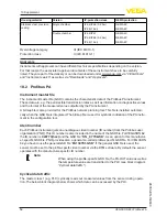
Page 54: ...nt A bitmap file is also provided for the Profibus network planning tool This file is installed automati cally when the GSD file is integrated The bitmap file is used for symbolic indication of the PA instru ment in the configuration tool Ident number Each Profibus instrument gets an unambiguous ident number ID number from the Profibus user organisation PNO This ID number is also included in the n...

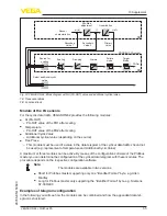
Page 55: ...itional cyclical value depending on the source Free Place This module must be used if a value in the data telegram of the cyclical data traffic should not be used e g replacement of temperature and Additional Cyclic Value A maximum of three modules can be active By means of the configuration software of the Profibus master you can determine the configuration of the cyclical data telegram with thes...

Page 56: ...ram configuration Byte No 1 2 3 4 5 6 7 8 9 10 Status Status Status Status FB1 IEEE 754 Floating point value PA OUT FB1 IEEE 754 Floating point value Additional Cyclic Value Format Value Data format of the output signal Byte4 Byte3 Byte2 Byte1 Byte0 Status Value IEEE 754 Fig 37 Data format of the output signal The status byte corresponds to profile 3 0 Profibus PA Profile for Process Control Devic...

Page 57: ...d al ready valid measured value since switching on 0 x 48 uncertain substitute set Switch on simulation Failsafe replacement value Failsafe Mode Fsafe value 0 x 4c uncertain initial value Failsafe replacement value Failsafe Mode Last valid value and no valid measured value since switching on 0 x 51 uncertain sensor conversion not accurate low limited Sensor value lower limit 0 x 52 uncertain senso...

Page 58: ... 72 M20x1 5 NPT 116 mm 4 57 ø 84 mm 3 31 116 mm 4 57 M20x1 5 M20x1 5 NPT 59 mm 2 32 ø 80 mm 3 15 112 mm 4 41 M20x1 5 NPT 1 5 3 6 2 4 Fig 39 Housing versions with protection rating IP 66 IP 68 0 2 bar with integrated display and adjustment module the housing is 9 mm 0 35 in higher 1 Plastic housing IP 66 IP 67 2 Aluminium housing 3 Aluminium double chamber housing 4 Stainless steel housing electrop...

Page 59: ...n with protection rating IP 66 IP 68 1 bar with integrated display and adjustment module the housing is 9 mm 0 35 in higher 1 Aluminium housing 2 Stainless steel housing precision casting 2 Stainless steel double chamber housing precision casting VEGASON 62 1 2 153mm 6 1 32 20mm 25 32 63mm 2 31 64 ø 50mm 1 31 32 ø 74mm 2 58 64 60mm 2 23 64 G2A 2 NPT Fig 41 VEGASON 62 1 Dead zone 0 4 m 1 312 ft 2 M...

Page 60: ...EGA sont globalement protégées par des droits de propriété intellec tuelle Pour plus d informations on pourra se référer au site www vega com VEGA lineas de productos están protegidas por los derechos en el campo de la propiedad indus trial Para mayor información revise la pagina web www vega com Линии продукции фирмы ВЕГА защищаются по всему миру правами на интеллектуальную собственность Дальнейш...

Page 61: ...61 Notes VEGASON 62 Profibus PA 28785 EN 150603 ...

Page 62: ...62 Notes VEGASON 62 Profibus PA 28785 EN 150603 ...

Page 63: ...63 Notes VEGASON 62 Profibus PA 28785 EN 150603 ...

Page 64: ...e of delivery application practical use and operat ing conditions of the sensors and processing systems correspond to the information available at the time of printing Subject to change without prior notice VEGA Grieshaber KG Schiltach Germany 2015 Phone 49 7836 50 0 Fax 49 7836 50 201 E mail info de vega com www vega com ...

Reviews: