background image

27

SpECIFICATIONS

Audio Sections

Power Output/Channel (2 channels driven into 8 Ω; remainder @ 1/8 rated power) 

35 Watts, 20Hz to 20kHz

THD (at rated power) 

<0.07% 

Power/Channel (2 channels driven into 4 Ω) 

55 Watts <0.1%THD @ 1kHz

Power/Channel (bridged mode driven into 8 Ω) 

110 Watts <0.5%THD @ 1kHz

Damping Factor (non-bridged mode) 

>130, all channels

Input Sensitivity (For rated power @ max VC) 

900 mVrms, All Inputs

Bus Loop Outputs 

900 mVrms, with 900 mVrms at Bus Inputs

Frequency Response (@ 1 Watt @ 8 Ω) 

9.5 Hz to 80 kHz 

+

-

 1.5 dB

Channel Separation 

> 50 dB @ 10 kHz

Cross Talk Between Channel Pair 

> 75 dB @ 10 kHz

S/N Ratio (Re: Rated Output, IEC A, Line Inputs 1k Ω) 

> 120 dB (VC 20 dB below FCW)

General

Control Sections

Auto ON Sensitivity / Time 

11 mV / 4 seconds

Auto OFF Sensitivity / Time 

<10 mV / 5 minutes

Control Out Voltage, unloaded / 100mA load 

12 VDC / 11.5 VDC

Trigger Input ON Voltage / Time 

3-24 VDC / 4 seconds

Trigger OFF Voltage / Time 

2.0 VDC / 2 seconds


Power Consumption

Standby 

3 Watts

No signal (idle) 

75 Watts   

At 

1

8

 Rated Power (4.38 Watts/Channel) 

270 Watts

Line Ratings 

120 VAC 

Rear Panel Marked Power Consumption 

770 Watts

Rear Panel Fuse 

T10AL/250V


Dimensions 

17-

3

4

” W x *5-

1

4

” H x 18-

1

2

” D


* 5-

7

8

” H, including feet

Weight 

34 lbs

Summary of Contents for M8

Page 1: ...Audio Systems M8 35W x 8 Channel Power Amplifier Installation User Guide ...

Page 2: ... or pinched by items placed upon or against them paying particular attention to cords at plugs convenience receptacles and at the point where they exit from the appliance 13 Cleaning The appliance should be cleaned only as recommended by the manufacturer 14 Power Lines An outdoor antenna should be located away from the power lines 15 Nonuse Periods The power cord of the appliance should be unplugg...

Page 3: ...ONS 12 BRIDGED MODE SPEAKER CONNECTIONS 13 connections Setup 14 AUDIO CONNECTIONS 14 Line IN 14 BUS IN BUS LOOP 14 AUX IN 15 BRIDGED MODE CONNECTIONS 16 POWER ON OFF MODES 17 Manual Power 17 Audio Sensing Auto On 17 Voltage Sensing Trigger 17 Control Out 18 AC Power Cord 18 LEVEL CONTROL 19 system applications 20 Multiroom 21 Home Theater Plus Second Zone 23 Multizone Mixed Use 25 troubleshooting ...

Page 4: ...al M8s for a total of up to twenty rooms of amplified audio Output configuration as eight mono four stereo two high power stereo output channels and some com binations of the three adds even more flexibility to M8 applications The M8s audio channels can be config ured for normal power output for up to eight mono or four stereo channels The amplifier channels are also bridgeable allowing two amplif...

Page 5: ...or four stereo inputs Bus Input can feed one stereo or two mono audio signal to all eight or specifically selected channels AUX In can feed a stereo or two mono signals to specifically selected left or right channels Outputs Eight five way binding posts for speaker connection BUS Loop can feed the BUS Input signal to additional amplifiers Bridgeable amplifier outputs for high power applications Co...

Page 6: ... output audio to con nected speakers on any channels with selected active audio input To turn the unit OFF press the button again and all audio signals will be cut the amp will turn off the Front Panel LEDs and the ON OFF button backlight will turn OFF 2 FRONT PANEL LEDs Eight red LEDs LEDs 1 4 will turn red if any one of channels 1 4 has shut down due to thermal over load short circuit or other i...

Page 7: ...the Channel Input switch to BUS L or BUS R Any source s mono or stereo connected to the BUS IN will also be fed to the BUS LOOP output for connection of additional M8s 6 BRIDGED ON OFF Four two position switches When set in the OFF position the associated channels 1 2 3 4 5 6 7 8 will be set to normal mode standard power discreet channel configuration 35W ch with one speaker connected to each Spea...

Page 8: ...1 3 5 7 and AUX R 2 4 6 8 10 FUSE Replaceable T10AL 250V fuse 11 AC INPUT Connect to the included IEC 2 prong AC Power Cord After all connections have been made and confirmed plug the power cord into an unswitched 110V AC Outlet to power the M8 Contact Proficient Audio Systems for a proper replace ment should the AC Power Cord be damaged or misplaced 12 SPEAKER TERMINALS Sixteen five way binding p...

Page 9: ...et hot with the heat generated by microprocessors and motors in vari ous devices Providing proper ventilation for good air flow will help keep the temperature down and protect not only the M8 but all system components and help preserve their longevity When installing the M8 a few easy steps should be taken to assure proper air flow 1 Never block the vent holes on the top or bottom of the M8 2 Neve...

Page 10: ...splay and at equal distances to left and right of the Video Display will create an effect where the sound emanates from the picture Inwall Speakers Ideally speaker placement should be similar to that described for bookshelf speakers Many brands of inwall speakers including most Proficient models have pivoting tweeters that can focus the high frequency content directly to the Ideal Listening Zone a...

Page 11: ...ontrolled zone preamps In this application each zone s stereo preamp output gets connected to a pair of channel inputs on the M8 Each zone s volume is controlled using a hand held remote or keypad so the volume control is not required Connecting the M8 for multizone audio requires that two pair of speaker wire be run from the M8 location directly to each speaker in home runs each run direct from t...

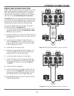
Page 12: ...s 6 7 1 Use 16AWG min 2 conductor stranded speaker wire for speaker connection Refer to the Speaker Wire Length Chart for wire runs over 150 2 Strip approximately 1 2 to 3 4 of an inch off the ends and twist the strands together so there are no loose ends that can cause shorts 3 Loosen the Channel 1 Speaker Terminals as shown in Dia gram 5 so there is enough room between the post and the collar to...

Page 13: ...1 2 to 3 4 of an inch off the ends and twist the strands together so there are no loose ends that can cause shorts 3 Loosen the Channel 5 Bridged Speaker Terminal as shown in Diagram 5 so there is enough room between the post and the collar to feed the striped wire through without damaging the strands 4 Tighten the post to secure the wire 5 Repeat for the appropriate Channel 5 8 bridged and termin...

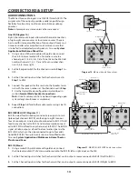
Page 14: ...n as described in section Normal Mode Speaker Connections Note Use of a volume control is optional depending upon system design multiroom vs multizone 5 Repeat Steps 1 4 for all other audio sources using Line IN connections BUS IN BUS LOOP Diagram 11 BUS IN is ideal for distributing mono or stereo signals to mul tiple output channels BUS IN can feed up to eight mono or four stereo outputs Line lev...

Page 15: ...LOOP can be connected to up to four additional M8s Also see System Applications Multiroom 1 Using a stereo patch cable with gold ends connect the BUS LOOP on M8 1 to the BUS IN on M8 2 2 Repeat Step 1 for all additional M8s Five M8s total 3 Follow Steps 1 4 in section BUS IN to configure the additional M8s AUX IN Diagram 12 AUX IN will feed stereo line level audio to any channel pair set to AUX L ...

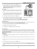
Page 16: ...o LINE Bridged Switch ON M8 Odd Number Channel Line IN Line OUT Bridged Switch ON Left Channel from Source Right Channel from Source Diagram 13 M8 Bridged Mode Audio Input Connections For example of bridged channel source connections Channels 5 8 same as those used in the bridged speaker connection dia grams will be used to connect a stereo device to two bridged channel pair 1 Using a stereo RCA p...

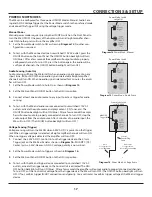
Page 17: ...ner etc The ON OFF button backlight will tun ON blue After a few seconds the ampli fier will output audio to properly connected channels To turn OFF stop the audio output from the audio source After 5 minutes of no audio input the M8 will turn OFF The ON OFF button backlight will turn OFF Voltage Sensing Trigger Voltage sensing will turn the M8 ON when 3 30V AC DC is present on the Trigger jack Wh...

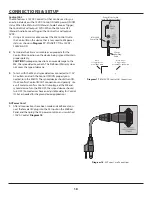
Page 18: ...t cover this type of damage 3 To test with the M8 and synced devices connected to 110V AC outlets and with the Control IN OUTs properly con nected turn the M8 ON The synced device should turn ON If not confirm Control IN OUT connections and polarity Use a volt meter to confirm Control Out voltage at the M8 and synced device Turn the M8 OFF the synced device should turn OFF Some devices have an adj...

Page 19: ...st M8 Level Controls turn the knobs counterclock wise left to reduce level Turn the knobs clockwise right to increase level For stereo applications in Normal Mode odd numbered channels are left even numbered channels are right In Dia M8 Channel Level Controls Left Channel Right Channel Diagram 19 M8 Level Controls Normal Mode M8 Left Channel Right Channel Bridged Channel Level Controls Diagram 20 ...

Page 20: ...peakers Room 2 Proficient VCS60 Volume Control Proficient C645 Ceiling Speakers Room 3 Proficient VCS60 Volume Control Proficient C645 Ceiling Speakers Room 4 16AWG min 2 Conductor Stranded Speaker Wire 16AWG min 2 Conductor Stranded Speaker Wire To Unswitched 110V AC Outlet Set Odd BUS Channel Input Switches to BUS L Even Channels to BUS R Set all Bridged Switches to OFF M8 BUS IN M8 BUS LOOP To ...

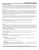
Page 21: ...o signal will output through any channel s that are set to BUS L left or BUS R right 1 Connect the M40 Pre OUT to the M8 BUS IN 2 Set the Channel Input switches for all channels that are to output the BUS IN to BUS L left and BUS R right Bus Loop The M8 BUS LOOP is a fixed line level audio output that can be used in a number of different ways In the example shown the BUS LOOP is being fed back to ...

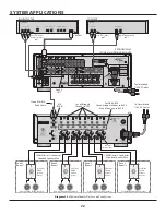
Page 22: ... 2 Room 4 16AWG min 2 Conductor Stranded Speaker Wire 16AWG min 2 Conductor Stranded Speaker Wire To Unswitched 110V AC Outlet Set Odd BUS Channel Input Switches to BUS L Even Channels to BUS R Set all Bridged Switches to OFF M8 BUS IN To Unswitched 110V AC Outlet Zone 2 OUT BLU RAY PLAYER CD PLAYER PROFICIENT M80 2 ZONE A V SURROUND RECEIVER M8 BLU RAY PLAYER DIGITAL AUDIO OUT OPTICAL COAXIAL L R...

Page 23: ...hat is connected to the M8 BUS IN The M8 BUS IN audio signal will output through any channel s that are set to BUS L left or BUS R right 1 Connect the M80 Zone 2 OUT to the M8 BUS IN 2 Set the Channel Input switches for all channels that are to output the BUS IN to BUS L left or BUS R right Bus Loop Source selection and audio processing for the home theater zone and Zone 2 are completely independe...

Page 24: ...AXIAL L R LINE LEVEL OUT Stereo RCA RCA Patch Cables Proficient VCS60 Volume Control Proficient C645 Ceiling Speakers Zone 2 Room 1 Proficient VCS60 Volume Control Proficient C645 Ceiling Speakers Zone 2 Room 2 Proficient C850 Ceiling Speakers Zone 4 16AWG min 2 Conductor Stranded Speaker Wire 16AWG min 2 Conductor Stranded Speaker Wire To Unswitched 110V AC Outlets Set Channel 1 2 3 4 Bridged Swi...

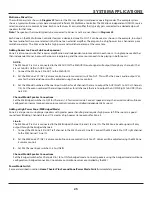
Page 25: ...o output Vol ume for the individual rooms will be adjusted using the volume controls 3 Set the M8 odd numbered Channel Input switches for all channels that are to output the AUX IN Left to AUX L Channels 1 3 Set the even numbered Channel Input switches for all channels that are to output the AUX IN Right to AUX R Chan nels 2 4 Channel Mode Speaker Connections Set the M8 Bridged switches to OFF for...

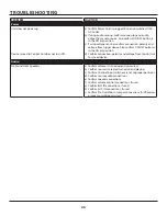
Page 26: ...r device Also confirm ON OFF button is in the ON in position d Confirm connection polarity and voltage from Control Out to synced device Audio No Sound From Speakers a Confirm volume is turned up and un muted b Confirm source is selected turned on and playing c Confirm Channel Input switches are set to proper positions d Confirm source audio connections e Confirm speaker connections f Confirm volu...

Page 27: ...Hz 1 5 dB Channel Separation 50 dB 10 kHz Cross Talk Between Channel Pair 75 dB 10 kHz S N Ratio Re Rated Output IEC A Line Inputs 1k Ω 120 dB VC 20 dB below FCW General Control Sections Auto ON Sensitivity Time 11 mV 4 seconds Auto OFF Sensitivity Time 10 mV 5 minutes Control Out Voltage unloaded 100mA load 12 VDC 11 5 VDC Trigger Input ON Voltage Time 3 24 VDC 4 seconds Trigger OFF Voltage Time ...

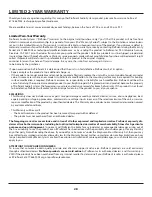
Page 28: ...SIONS This Warranty does not include service or parts to repair damage caused by accident disaster misuse abuse negligence inad equate packing or shipping procedures commercial use voltage inputs in excess of the rated maximum of the unit or service repair or modification of the product by unauthorized dealers This Warranty also excludes normal cosmetic deterioration caused by environmental condit...

Page 29: ...29 notes ...

Page 30: ...30 notes ...

Page 31: ...31 notes ...

Page 32: ...Audio Systems 940 Columbia Avenue Riverside CA 92507 877 888 9004 Fax 951 750 6304 proficientaudio com 2009 Proficient Audio Systems 1301 72800 ...

Reviews: