background image

27

E N G L I S H

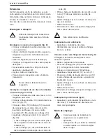
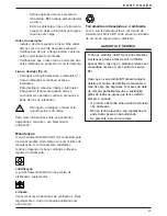
Labels on tool
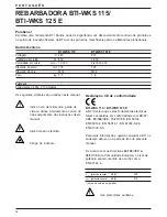
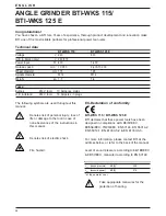
The following pictographs are shown on the tool:

Read the instruction manual before use

Wear safety glasses

Wear ear protection

Package contents

The package contains:

1 Angle grinder
1 Guard
1 Side handle
1 Flange set
1 Two-pin spanner
1 Instruction manual
1 Exploded drawing

• Check for damage to the tool, parts or

accessories which may have occurred during
transport.

• Take the time to thoroughly read and

understand this manual prior to operation.

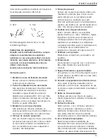
Description (fig. A)

Your angle grinder has been designed for
professional grinding and cutting applications.

1 On/off switch
2 Speed control dial (BTI-WKS 125 E)
3 Spindle lock
4 Guard
5 Side handle

BTI-WKS 125 E - Soft start feature
The soft start feature allows a slow speed build-up
to avoid an initial jerk when starting. This feature is
particularly useful when working in confined
spaces.

Electrical safety

The electric motor has been designed for one
voltage only. Always check that the power supply
corresponds to the voltage on the rating plate.

Your BTI tool is double insulated in
accordance with EN 50144; therefore
no earth wire is required.

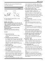
Mains plug replacement
(U.K. & Ireland only)

• Should your mains plug need replacing and you

are competent to do this, proceed as instructed
below. If you are in doubt, contact an
authorized BTI repair agent or a qualified
electrician.

• Disconnect the plug from the supply.
• Cut off the plug and dispose of it safely; a plug

with bared copper conductors is dangerous if
engaged in a live socket outlet.

• Only fit 13 Amperes BS1363A approved plugs

fitted with the correctly rated fuse (1).

• The cable wire colours, or a letter, will be

marked at the connection points of most good
quality plugs. Attach the wires to their
respective points in the plug (see below).
Brown is for Live (L) (2) and Blue is for Neutral
(N) (4).

• Before replacing the top cover of the mains

plug ensure that the cable restraint (3) is
holding the outer sheath of the cable firmly and
that the two leads are correctly fixed at the
terminal screws.

Never use a light socket.
Never connect the live (L) or neutral (N)
wires to the earth pin marked E or  .

For 115 V units with a power rating exceeding
1500 W, we recommend to fit a plug to BS4343
standard.

Using an extension cable

If an extension cable is required, use an approved
extension cable suitable for the power input of this

Summary of Contents for BTI-WKS 115

Page 1: ...BTI T cnicas de la fijaci n S L Pol Ind Nirsa C Partida de la grasa Nave B 4 E 43206 Reus Tarragona Telefon 977 77 51 84 Telefax 977 77 12 56 Leipzig Wahren Pittlerstra e 33 04159 Leipzig Telefon 034...

Page 2: ...1 Deutsch 5 Espa ol 12 Portugu s 18 English 24 Copyright BTI...

Page 3: ...2 A 1 3 4 5 2...

Page 4: ...3 B C2 D C1...

Page 5: ...4 17 5 17 E...

Page 6: ...gende Symbole werden in dieser Anleitung verwendet Achtung Verletzungsgefahr Lebensgefahr oder m gliche Besch digung des Elektrowerkzeuges infolge der Nichtbeachtung der Anweisungen dieser Anleitung E...

Page 7: ...ie immer eine Schutzbrille Tra gen Sie eine Atemschutzmaske falls die Arbei ten Staub oder Sp ne erzeugen k nnen Falls diese Teilchen hei sind so m ssen Sie auch eine hitzebest ndige Sch rze tragen Tr...

Page 8: ...benutzen bevor Sie irgendwelche Werkzeuge Zubeh rteile oder Ger teteile auswechseln und bevor Sie irgendwelche Wartungsarbeiten vornehmen 16 Vermeiden Sie ein unbeabsichtigtes Einschalten Tragen Sie d...

Page 9: ...e entz nden Benutzen Sie das Werkzeug nicht w hrend Sie sich in Reihe zur Scheibe befinden Halten Sie andere Personen vom Arbeitsbereich fern Verwenden Sie keine Trennscheiben f r seitliches Schleifen...

Page 10: ...nenfalls die Spannkraft indem Sie die Schraube 9 anziehen Ziehen Sie die Sicherungsklammer fest Um die Schutzvorrichtung zu entfernen l sen Sie die Sicherungsklammer Verwenden Sie das Werkzeug niemals...

Page 11: ...Trennscheibe in Pfeilrichtung siehe Zubeh r teil und Werkzeug dreht Ein und Ausschalten Abb A Dr cken Sie zum Einschalten den Ein Aus Schalter F r Dauerbetrieb dr cken Sie den Ein Ausschalter ganz na...

Page 12: ...n Zentralkundendienst oder an die n chste BTI Kundendienstwerkstatt Die Garantiezeit von 12 Monaten beginnt mit dem Kaufdatum das durch den Original Kaufbeleg nachgewiesen werden mu In dieser Zeit gar...

Page 13: ...entes Indica peligro de lesiones de accidentes mortales o de aver as en la herramienta en caso de no respeto de las instrucciones en este manual Indica tensi n el ctrica Peligro de incendio Declaraci...

Page 14: ...ejecutado produce polvo u otro tipo de part culas que puedan ser inhaladas Si esas part culas est n a unatemperatura considerablemetne caliente utilice tambi n un delantal de trabajo Lleve puesta siem...

Page 15: ...eg rese de que la herramienta est apagada cuando la enchufe 17 No someta el cable de alimentaci n a presi n innecesaria No sostenga nunca la herramienta por el cable Nunca tire del cable para desconec...

Page 16: ...corte en lugares secos Etiquetas sobre la herramienta En la herramienta se indican los siguientes pictogramas Antes de usar leer el manual de instrucciones Lleve gafas de protecci n Use protecci n ac...

Page 17: ...muela A el aro de la brida 14 debe quedar hacia el lado contrario al disco cuando se instala un disco de corte B Presione el bloqueo del eje 3 y haga girar el eje 11 hasta que encaje en su posici n A...

Page 18: ...rramienta el ctrica BTI ha sido dise ada para funcionar mucho tiempo con un m nimo de mantenimiento El funcionamiento satisfactorio depende del buen cuidado de la herramienta y de una limpieza frecuen...

Page 19: ...neste manual Indica risco de ferimentos perda de vida ou danos ferramenta no caso do n o cumprimento das instru es deste manual Indica tens o el ctrica Perigo de inc ndio Declara o CE de conformidade...

Page 20: ...ira ou part culas que voem Caso tais part culas sejam consideravelmente quentes use tamb m um avental resistente ao calor Use sempre protectores auriculares 6 Cuidado com choques el ctricos Evite o co...

Page 21: ...s ferramentas que n o estiverem em uso Guarde as ferramentas que n o estiverem em uso em lugar seco Feche as com seguran a fora do alcance das crian as 19 Cuide das suas ferramentas com aten o Para um...

Page 22: ...lize culos de protec o Utilize protec es auriculares Verifica o do conte do da embalagem A embalagem cont m 1 Rebarbadora 1 Resguardo 1 Punho lateral 1 Flange 1 Chave de dois pinos 1 Manual de instru...

Page 23: ...r virado para o disco aquando da coloca o de um disco de rebarbar A o anel na flange 14 deve ficar afastado do disco aquando da coloca o de um disco de corte B Prima o bot o de travamento do veio 3 e...

Page 24: ...El ctrica BTI foi concebida para funcionar durante muito tempo com um m nimo de manuten o O funcionamento satisfat rio cont nuo depende de bons cuidados e limpeza regular da ferramenta Lubrifica o A s...

Page 25: ...owing symbols are used throughout this manual Denotes risk of personal injury loss of life or damage to the tool in case of non observance of the instructions in this manual Denotes risk of electric s...

Page 26: ...ction at all times 6 Guard against electric shock Prevent body contact with earthed surfaces e g pipes radiators cookers and refrigerators When using the tool under extreme conditions e g high humidit...

Page 27: ...itional safety rules for grinders Your grinder has been designed for grinding and cutting masonry and steel Do not cut or grind light metal with a magnesium content exceeding 80 since this type of met...

Page 28: ...ance with EN 50144 therefore no earth wire is required Mains plug replacement U K Ireland only Should your mains plug need replacing and you are competent to do this proceed as instructed below If you...

Page 29: ...inner flange 10 correctly onto the spindle 11 fig C1 Place the disc 12 on the flange 10 When fitting a disc with a raised center make sure that the raised centre 13 is facing the flange 10 Screw the...

Page 30: ...BTI Power Tool has been designed to operate over a long period of time with a minimum of maintenance Continuous satisfactory operation depends upon proper tool care and regular cleaning Lubrication Yo...

Page 31: ...30...

Page 32: ...31...

Page 33: ...32 622331 00...

Reviews: