28
E N G L I S H
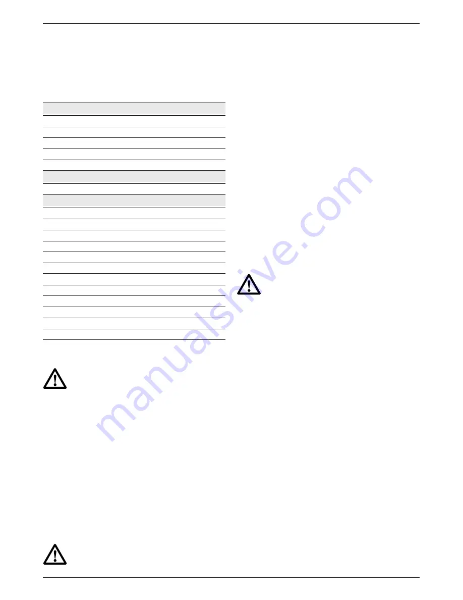
tool (see technical data). The minimum conductor
size is 1.5 mm
2
.
When using a cable reel, always unwind the cable
completely.
Also refer to the table below.
Conductor size (mm
2
) Cable rating (Amperes)
0.75
6
1.00
10
1.50
15
2.50
20
4.00
25
Cable length (m)
7.5
15
25
30
45
60
Voltage
Amperes
Cable rating (Amperes)
115
0 - 2.0
6
6
6
6
6
10
2.1 - 3.4
6
6
6
6
15
15
3.5 - 5.0
6
6
10
15
20
20
5.1 - 7.0
10
10
15
20
20
25
7.1 - 12.0
15
15
20
25
25
-
12.1 - 20.0
20
20
25
-
-
-
230
0 - 2.0
6
6
6
6
6
6
2.1 - 3.4
6
6
6
6
6
6
3.5 - 5.0
6
6
6
6
10
15
5.1 - 7.0
10
10
10
10
15
15
7.1 - 12.0
15
15
15
15
20
20
12.1 - 20.0
20
20
20
20
25
-
Assembly and adjustment
Prior to assembly and adjustment
always unplug the tool.
Mounting and removing the guard (fig. B)
• Place the angle grinder on a table, spindle up.
• Release the clamping lock (6) and hold the
guard (4) over the tool as shown.
• Align the lugs (7) with the notches (8).
• Press the guard down and rotate it to the
required position.
• If required, increase the clamping force by
tightening the screw (9).
• Tighten the clamping lock.
• To remove the guard, release the clamping
lock.
Never use the tool without the guard in
place.
Fitting and removing a grinding or cutting disc
(fig. C1 & C2)
• Place the tool on a table, guard up.
• Fit the inner flange (10) correctly onto the
spindle (11) (fig. C1).
• Place the disc (12) on the flange (10). When
fitting a disc with a raised center, make sure that
the raised centre (13) is facing the flange (10).
• Screw the outer flange (14) onto the spindle
(11) (fig. C2):
- the ring on the flange (14) must face towards
the disc when fitting a grinding disc (A);
- the ring on the flange (14) must face away
from the disc when fitting a cutting disc (B).
• Press the spindle lock (3) and rotate the
spindle (11) until it locks in position.
• Tighten the flange (14) with the two-pin
spanner supplied.
• Release the spindle lock.
• To remove the disc, loosen the flange (14) with
the two-pin spanner.
Do not use a damaged disc.
Fitting a wire cup brush
• Screw the wire cup brush directly onto the
spindle without using the spacer and threaded
flange.
Mounting and removing the rubber backing
pad (fig. D)
The rubber backing pad is available as an option.
• Remove the guard from the tool.
• Press the backing pad (15) onto the spindle
(11). The inner flange is not needed.
• Position the abrasive disc (16) on the pad.
• Screw the outer flange (14) onto the spindle
(11).
• Press the spindle lock and rotate the pad (15)
until it locks in position.
• Tighten the flange (14) using the two-pin
spanner supplied.
• Release the spindle lock.
• To remove the pad, loosen the flange (14) with
the two-pin spanner.
Mounting the side handle (fig. E)
• Screw the side handle (5) tightly into one of the
holes (17) on either side of the gear case.
Summary of Contents for BTI-WKS 115
Page 2: ...1 Deutsch 5 Espa ol 12 Portugu s 18 English 24 Copyright BTI...
Page 3: ...2 A 1 3 4 5 2...
Page 4: ...3 B C2 D C1...
Page 5: ...4 17 5 17 E...
Page 31: ...30...
Page 32: ...31...
Page 33: ...32 622331 00...


