background image

14

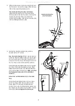
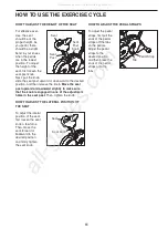
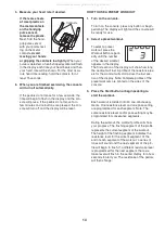
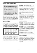
5. Measure your heart rate if desired.

If there are sheets

of clear plastic on

the metal contacts

on the handgrip

pulse sensor,

remove the plastic.

Next, hold the hand-

grip pulse sensor

with your palms rest-

ing on the metal

contacts.

Avoid

moving your hands

or gripping the contacts too tightly.

When your

pulse is detected, a heart-shaped symbol will flash

in the display each time your heart beats and then

your heart rate will be shown. For the most accu-

rate heart rate reading, hold the contacts for at

least 15 seconds.

6. When you are finished exercising, the console

will turn off automatically.

If the pedals do not move for a few seconds, the

time will begin to flash in the display and the con-

sole will pause. If the pedals do not move for a

few minutes and no buttons are pressed, the con-

sole will turn off and the display will be reset.

HOW TO USE A PRESET WORKOUT

1. Turn on the console.

To turn on the console, press any button or begin

pedaling. The display will light and the console will

be ready for use.

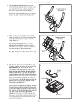
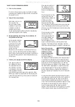
2. Select a preset workout.

To select a preset

workout, press the

Workout button repeat-

edly until the number

of the desired workout

appears in the display.

The first section of the display will show how long

the workout will last. A profile of the resistance lev-

els for the workout will scroll across the last sec-

tion of the display. Note: Complete profiles of the

preset workouts are printed on the sides of the

console.

3. Press the Start button or begin pedaling to

start the workout.

Each workout is divided into 30 one-minute seg-

ments. One resistance level and one pace setting

are programmed for each segment. Note: The

same resistance level and/or pace setting may be

programmed for consecutive segments.

During the workout, the workout profile will show

your progress. The flashing segment of the profile

represents the current segment of the workout.

The height of the flashing segment indicates the

resistance level for the current segment. At the

end of each segment of the workout, a series of

tones will sound and the next segment of the pro-

file will begin to flash. If a different resistance level

is programmed for the next segment, the resis-

tance level will flash in the center display for a few

seconds to alert you. The resistance of the pedals

will then change.

Contacts

All manuals and user guides at all-guides.com

Summary of Contents for 180 Ur Bike

Page 1: ...cturer we are commit ted to providing complete customer satisfaction If you have questions or if parts are missing DO NOT CONTACT THE STORE please contact Customer Care IMPORTANT You must note the pro...

Page 2: ...NG REPLACEMENT PARTS Back Cover LIMITED WARRANTY Back Cover WARNING DECAL PLACEMENT This drawing shows the location s of the warning decal s If a decal is missing or illegible see the front cover of t...

Page 3: ...the exercise cycle 5 Inspect and properly tighten all parts regular ly Replace any worn parts immediately 6 Keep children under age 12 and pets away from your exercise cycle at all times 7 Your exerci...

Page 4: ...of features designed to make your workouts at home more effec tive and enjoyable For your benefit read this manual carefully before you use the exercise cycle If you have questions after reading this...

Page 5: ...ed area and remove the pack ing materials Do not dispose of the packing materials until assembly is completed In addition to the included tool s assembly requires a Phillips screwdriver and an adjusta...

Page 6: ...r person lifts the rear of the Frame 1 attach the Rear Stabilizer to the Frame with two M10 x 54mm Patch Screws 33 and two M10 Split Washers 34 3 While another person lifts the front of the Frame 1 at...

Page 7: ...er Bottle Holder 49 as shown Insert the Upper Wire Harness 32 and the Pulse Wires 71 through the Water Bottle Holder Then slide the Water Bottle Holder onto the Upright 3 and attach it with an M4 x 16...

Page 8: ...e four D batteries not included alkaline batteries are recommended IMPORTANT If the Console has been exposed to cold temperatures allow it to warm to room temperature before inserting batteries Otherw...

Page 9: ...one of the adjustment holes in the Seat Post Then tighten the Seat Post Knob 9 5 1 30 10 10 Orient the Seat 12 and the Seat Carriage 29 as shown Attach the Seat 12 to the Seat Carriage 29 with four M8...

Page 10: ...into the right arm of the Crank 13 Tighten the Left Pedal not shown counterclockwise into the left arm of the Crank IMPORTANT Tighten both pedals as firmly as possible After using the exercise cycle f...

Page 11: ...e knob is engaged in one of the adjustment holes in the seat post Then tighten the knob HOW TO ADJUST THE LATERAL POSITION OF THE SEAT To adjust the lateral position of the seat first loosen the seat...

Page 12: ...and prompts you to increase or decrease your pedaling pace as it guides you through an effective workout The console features the iFit Interactive Workout System which enables the console to accept iF...

Page 13: ...e burned and the resis tance level of the ped als The display will change modes every few sec onds The display will also show your heart rate when you use the handgrip pulse sensor see step 5 on page...

Page 14: ...ss the Workout button repeat edly until the number of the desired workout appears in the display The first section of the display will show how long the workout will last A profile of the resistance l...

Page 15: ...w workout 4 Follow your progress with the display See step 4 on page 13 5 Measure your heart rate if desired See step 5 on page 14 6 When you are finished exercising the console will turn off automati...

Page 16: ...emove the left shield Locate the Reed Switch 21 Turn the Crank 13 until a Magnet 16 is aligned with the Reed Switch Next loosen but do not remove the indicated M4 x 16mm Flange Screw 61 Slide the Reed...

Page 17: ...n your cardiovascular system you must perform aerobic exercise which is activity that requires large amounts of oxygen for prolonged periods of time For aerobic exercise adjust the intensity of your e...

Page 18: ...44 1 Long C magnet Spacer 45 1 M10 x 22mm Bolt 46 1 C magnet 47 1 Left Handlebar 48 1 Right Handlebar 49 1 Water Bottle Holder 50 2 M8 x 25mm Patch Screw 51 2 Handlebar Cap 52 1 M10 Locknut 53 4 M6 x...

Page 19: ...48 53 53 54 7 8 12 17 18 27 19 15 25 25 11 67 34 34 34 34 36 36 36 36 36 37 38 39 40 40 40 40 49 50 54 55 56 57 58 59 60 61 62 40 40 63 63 64 71 65 65 40 74 75 74 75 43 43 43 43 41 66 66 61 22 68 66...

Page 20: ...d by ICON ICON is not responsible or liable for indirect special or consequential damages arising out of or in con nection with the use or performance of the product damages with respect to any econom...

Reviews: