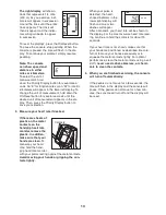
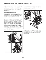
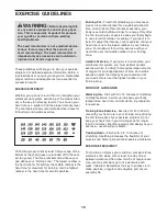
background image

15

ADJUSTING THE REED SWITCH

If the console does not display correct feedback, the

reed switch should be adjusted.

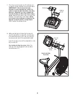
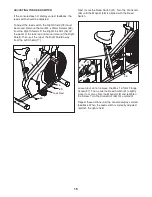
To adjust the reed switch, the Right Shield (18) must

be moved. Remove the four M4 x 25mm Screws (69)

from the Right Shield. Lift the Right Link Arm (16) off

the pedal or the lock rod and move it clear of the Right

Shield. Then, pull the top of the Right Shield away

from the Left Shield (17).

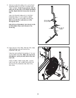
Next, locate the Reed Switch (31). Turn the Crank Arm

(26) until the Magnet (48) is aligned with the Reed

Switch.

Loosen, but do not remove, the M4 x 12.7mm Flange

Screw (27). Then, slide the Reed Switch (31) slightly

closer to or away from the Magnet (48) and retighten

the Screw. Turn the Crank Arm (26) for a moment.

Repeat these actions until the console displays correct

feedback. When the reed switch is correctly adjusted,

reattach the right shield.

26

27

32

69

18

17

69

Lock Rod

16

69

31

48

Summary of Contents for 29859.0

Page 1: ...No 29859 0 Serial No Write the serial number in the space above for reference QUESTIONS If you have questions or if parts are damaged or missing PLEASE CONTACT OUR CUSTOMER SER VICE DEPARTMENT DIRECT...

Page 2: ...LODED DRAWING 19 ORDERING REPLACEMENT PARTS Back Cover LIMITED WARRANTY Back Cover WARNING DECAL PLACEMENT This drawing shows the location s of the warning decal s If a decal is missing or illegible s...

Page 3: ...do not wear loose clothes that could become caught on the exercise bike Always wear athletic shoes for foot protection 10 The exercise bike should not be used by persons weighing more than 250 lbs 11...

Page 4: ...features designed to let you enjoy this healthful exercise in the comfort and privacy of your home For your benefit read this manual carefully before you use the exercise bike If you have questions af...

Page 5: ...terials Do not dispose of the packing materials until assembly is completed In addition to the included tool s assembly requires an adjustable wrench and a Phillips screwdriver Use the drawings below...

Page 6: ...ard insert the Seat Post 6 into the Frame 1 and then release the Seat Knob Move the Seat Post upward and downward slightly to make sure that the pin on the Seat Knob is engaged in one of the adjustmen...

Page 7: ...amount of the included grease to the Handlebar Axle 33 Insert the Handlebar Axle into the Frame 1 and center it 5 31 1 Grease 33 Avoid pinching the Reed Switch Wire 31 6 6 While another person holds t...

Page 8: ...ry compartment Make sure to orient the batteries as shown by the diagram inside the battery compartment Then reattach the battery cover 3 Battery Cover Batteries 7 8 3 Console Wire Ground Wire 8 While...

Page 9: ...49 78 78 33 85 85 84 84 9 9 Identify the Right Handlebar 9 and the Right Handlebar Base 10 which are marked with Right stickers Orient these parts so that the wide side of the tube on the Right Handle...

Page 10: ...g Make sure that there is a Custom Washer 86 a Pedal Spring 42 a Blue Washer 71 a Pedal Bushing 43 a Black Pedal Washer 79 and a Pedal Spacer 44 on the shaft of the Pedal In addition make sure that th...

Page 11: ...stationary mode the link arms must be disconnected from the pedals Pull the link arms outward against the blue washers until the link arms are free of the pedal bushings see drawing 2 at the left Be...

Page 12: ...d The lower right dis play can show your pedaling speed in miles or kilometers per hour and the approxi mate number of calories you have burned When you use the handgrip heart rate monitor the lower r...

Page 13: ...plastic on the metal contacts on the handgrip heart rate monitor remove the plastic In addition make sure that your hands are clean To measure your heart rate hold the hand grip heart rate monitor wi...

Page 14: ...ight the bearings may be damaged if the belt is too loose the fan may be damaged If the belt causes excessive noise or slips as you pedal follow the steps below Carefully remove the four Guard Clips 7...

Page 15: ...ll the top of the Right Shield away from the Left Shield 17 Next locate the Reed Switch 31 Turn the Crank Arm 26 until the Magnet 48 is aligned with the Reed Switch Loosen but do not remove the M4 x 1...

Page 16: ...goal is to strengthen your cardiovascular system you must perform aerobic exercise which is activity that requires large amounts of oxygen for prolonged periods of time For aerobic exercise adjust the...

Page 17: ...lles Stretch With one leg in front of the other reach forward and place your hands against a wall Keep your back leg straight and your back foot flat on the floor Bend your front leg lean forward and...

Page 18: ...net 49 2 Small Axle Cover 50 2 Small Axle Cap 51 1 Fan Washer 52 2 Eyebolt 53 2 M6 Nut 54 3 M10 Split Washer 55 3 M10 x 17mm Screw 56 4 M6 Locknut 57 4 M6 x 38mm Button Bolt 58 2 M8 x 74mm Button Bolt...

Page 19: ...32 30 33 34 34 34 34 34 34 35 35 36 37 37 38 38 39 40 41 41 42 43 44 42 43 44 45 45 46 47 48 49 78 50 50 74 51 52 53 52 53 54 54 55 55 56 56 57 57 58 58 59 64 66 66 65 66 67 68 67 68 62 27 69 69 69 6...

Page 20: ...For in home service the customer will be responsible for a minimal trip charge This warranty does not extend to freight damage to the product This warranty will automatically be voided if the product...

Reviews: