background image

50

8

38

7

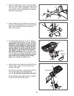
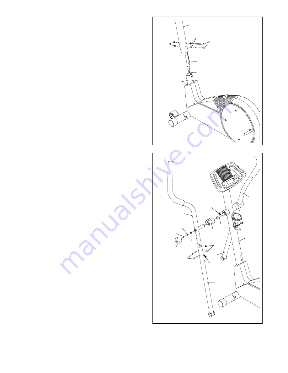
6. Identify the Left Handlebar (6), which is marked with

a sticker. Insert the Left Handlebar into one of the
Handlebar Legs (5); 

make sure that the Handlebar

Leg is turned so the hexagonal holes are on the
indicated side

. Attach the Left Handlebar to the

Handlebar Leg with two M8 x 45mm Button Bolts
(50) and two M8 Nylon Locknuts (38). 

Make sure

that the Nylon Locknuts are inside of the hexag-
onal holes. Do not tighten the Button Bolts yet.

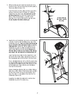
Insert the Pivot Axle (26) into the Upright (2), and
center the Pivot Axle. Apply a generous amount of
the included grease to both ends of the Pivot Axle. 

Turn a Handlebar Spacer (47) so that the small arrow
on the Handlebar Spacer is pointing toward the floor,
and slide the Handlebar Spacer onto the post on the
Left Handlebar (6). Next, slide the Left Handlebar
onto the Pivot Axle (26). 

Slide a Handlebar Washer (55) and a Wave Washer
(69) onto an M8 x 25mm Patch Screw (56), and tight-
en the Patch Screw into the Pivot Axle (26). Then,
press the tabs on a Handlebar Cap (46) into the
Handlebar Spacer (47).

Assemble the Right Handlebar (8) and the other
Handlebar Leg (5) in the same way.

Grease

6

47

5

2

5

55

46

26

56

69

6

Hexagonal

Holes

5

1

2

33

Avoid pinching

the wires during

this step

73

68

7

45

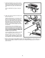
5. While another person holds the Upright (2) in the

position shown, connect the Extension Wire (68) to
the Lower Wire Harness (73). 

Push the Extension Wire (68) and the Lower Wire
Harness (73) down into the Frame (1). Slide the
Upright (2) onto the Frame. 

Be careful to avoid

pinching the Wires.

Attach the Upright with two

M10 x 74mm Button Bolts (7), two M10 Split
Washers (45), and two M10 Nylon Locknuts (33).

Do not tighten the Button Bolts yet.

Summary of Contents for 320 Elliptical

Page 1: ...Serial No Write the serial number in the space above for reference QUESTIONS As a manufacturer we are commit ted to providing complete customer satisfaction If you have questions or if parts are dama...

Page 2: ...ORDERING REPLACEMENT PARTS Back Cover LIMITED WARRANTY Back Cover 2 PROFORM is a registered trademark of ICON IP Inc WARNING DECAL PLACEMENT The warning decal shown here has been applied in the locati...

Page 3: ...enough clearance around your elliptical exerciser to mount dismount and use it 5 Inspect and properly tighten all parts regu larly Replace any worn parts immediately 6 Keep children under age 12 and...

Page 4: ...u have ques tions after reading this manual please see the front cover of this manual To help us assist you note the product model number and serial number before con tacting us The model number and t...

Page 5: ...requires two persons Place all parts of the elliptical exerciser in a cleared area and remove all packing materials do not dispose of the packing materials until assembly is completed Assembly requir...

Page 6: ...eries into the Console Make sure that the batteries are orient ed as shown by the markings on the battery cover Then reattach the battery cover 23 Batteries Batteries Battery Cover 3 4 While another p...

Page 7: ...Spacer onto the post on the Left Handlebar 6 Next slide the Left Handlebar onto the Pivot Axle 26 Slide a Handlebar Washer 55 and a Wave Washer 69 onto an M8 x 25mm Patch Screw 56 and tight en the Pa...

Page 8: ...dal Leg Hold the lower end of the left Handlebar Leg 5 inside of the bracket on the front of the Left Pedal Leg 11 Next apply grease to an M6 Bolt Set 25 Attach the Handlebar Leg to the Left Pedal Leg...

Page 9: ...ve the pedal discs in the direction shown by the arrow however for variety you can turn the pedal discs in the opposite direction To dismount the elliptical exerciser wait until the ped als come to a...

Page 10: ...ance levels The selected resistance level will be shown in the upper display Note After a button is pressed it will take a moment for the pedals to reach the selected resistance level 3 Follow your pr...

Page 11: ...e will be shown For the most accurate heart rate reading continue to hold the handgrips for about 30 seconds Note When you first hold the handgrips the display will show your heart rate continuously f...

Page 12: ...ve the Right Side Shield 4 Remove all Screws 52 from the Left Side Shield 3 and move the Left Side Shield Next see the drawing below and locate the Reed Switch 53 Loosen but do not remove the indicate...

Page 13: ...ur goal is to strengthen your cardiovascular system you must perform aerobic exercise which is activity that requires large amounts of oxygen for prolonged periods of time For aerobic exercise adjust...

Page 14: ...10 Nylon Locknut 34 4 M10 x 75mm Carriage Bolt 35 4 M10 Washer 36 2 M3 x 16mm Screw 37 2 Pedal Arm Bushing 38 5 M8 Nylon Locknut 39 2 Inside Pedal Arm Bushing 40 2 M10 x 27mm Patch Screw 41 2 M6 x 18m...

Page 15: ...33 51 15 70 34 9 33 33 20 20 16 61 54 52 53 38 65 62 55 56 38 50 48 47 49 24 56 55 57 35 33 58 21 21 34 60 60 60 23 52 52 64 52 41 52 41 64 49 48 47 49 49 46 16 42 25 25 25 25 15 66 66 35 67 7 45 59 9...

Page 16: ...ential damages arising out of or in con nection with the use or performance of the product or damages with respect to any economic loss loss of property loss of revenues or profits loss of enjoyment o...

Reviews: