background image

21

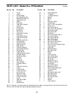
PART LIST—Model No. PFEL3906.0

R0807B

Note: “#” indicates a non-illustrated part. Specifications are subject to change without notice. See the back cover
of this manual for information about ordering replacement parts.

1

1

Frame

2

1

Upright

3

1

Front Stabilizer

4

1

Left Upper Body Arm

5

1

Right Upper Body Arm

6

2

Upper Body Leg

7

2

Sleeve

8

2

Foam Grip

9

2

Upper Body Endcap

10

1

Console

11

4

Wheel Cover

12

2

Leveling Foot

13

2

M4 Washer

14

2

Pivot Cover

15

6

Upper Body Bushing

16

1

Pivot Axle

17

1

Water Bottle Holder

18

1

Upper Wire Harness

19

2

Pedal

20

2

Large Wave Washer

21

1

Left Pedal Arm

22

1

Right Pedal Arm

23

2

Pedal Leg Cover

24

2

Ramp Wheel

25

4

Pedal Leg Bearing

26

4

Ramp Wheel Bushing

27

2

Wave Washer

28

2

Upright Spacer

29

2

Upper Body Arm Spacer

30

1

Left Side Shield

31

1

Right Side Shield

32

1

Left Disc

33

1

Right Disc

34

2

Disc Cover

35

1

Rear Stabilizer

36

4

Stabilizer Endcap

37

1

Belt

38

1

Lower Wire Harness

39

1

Crank

40

2

Crank Bearing

41

2

Crank Snap Ring

42

1

Left Crank Arm

43

1

Right Crank Arm

44

1

Resistance Cable

45

2

Crank Arm Spacer

46

1

Clamp

47

1

Reed Switch/Wire

48

1

Flywheel

49

1

Flywheel Axle

50

2

Flywheel Bearing

51

1

“C” Magnet

52

1

“C” Magnet Bracket

53

1

Magnet

54

1

Spring

55

1

Idler

56

1

Resistance Motor

57

2

Flange Screw

58

4

M10 x 77mm Carriage Bolt

59

4

Ramp Cover

60

13

M4 x 16mm Screw

61

1

M8 x 19mm Flat Head Bolt

62

1

Adjustment Screw

63

1

M6 x 18mm Bolt

64

6

M8 Washer

65

4

M5 x 16mm Button Screw

66

2

M4 x 22mm Screw

67

2

M8 x 63mm Bolt Set

68

6

M4 x 19mm Screw

69

4

M4 x 12mm Screw

70

6

M8 x 25mm Patch Screw

71

8

M5 x 25mm Screw

72

1

M4 x 12mm Round Head Screw

73

4

Ramp Bushing

74

1

Ramp Axle

75

12

M6 Star Washer

76

1

M6 x 38mm Bolt

77

1

M6 Nut

78

1

Ramp

79

2

Frame Bushing

80

1

M4 x 25mm Screw

81

2

M8 Large Washer

82

4

M4 Washer

83

1

M6 Nylon Locknut

84

7

M10 Nylon Locknut

85

6

Star Washer

86

2

M4 x 20mm Screw

87

4

M8 Nylon Locknut

88

2

M10 x 60mm Button Bolt

89

2

Transport Wheel

90

1

Ramp Pin

91

2

M8 x 69mm Button Bolt

92

2

M5 x 6mm Screw

93

2

M8 Split Washer

94

2

M3 x 16mm Screw

#

3

Hex Key

#

1

Grease

#

1

User’s Manual

Key No. Qty.

Description

Key No. Qty.

Description

Summary of Contents for 400 H Elliptical

Page 1: ... our website at www proform com new products prizes fitness tips and much more USER S MANUAL QUESTIONS As a manufacturer we are com mitted to providing complete customer satisfaction If you have questions or if parts are damaged or missing PLEASE CONTACT OUR CUSTOMER SERVICE DEPARTMENT DIRECTLY CALL TOLL FREE 1 888 533 1333 Mon Fri 6 a m 6 p m MST ON THE WEB www proformservice com ...

Page 2: ... ASSEMBLY 5 HOW TO USE THE ELLIPTICAL EXERCISER 12 MAINTENANCE AND TROUBLESHOOTING 17 CONDITIONING GUIDELINES 18 PART LIST 21 EXPLODED DRAWING 22 HOW TO ORDER REPLACEMENT PARTS Back Cover LIMITED WARRANTY Back Cover PROFORM is a registered trademark of ICON IP Inc ...

Page 3: ...cal exerciser at all times 8 The elliptical exerciser should not be used by persons weighing more than 250 pounds 9 When mounting or dismounting the elliptical exerciser always hold the upper body arms and step onto and off the pedal that is in the lowest position 10 The pulse sensor is not a medical device Various factors may affect the accuracy of heart rate readings The pulse sensor is intended...

Page 4: ...anual To help us assist you note the product model number and serial number before con tacting us The model number is PFEL3906 0 The serial number can be found on a decal attached to the elliptical exerciser see the front cover of this manual To avoid a registration fee for any service needed under warranty you must register the elliptical exerciser at www proformservice com registration Before re...

Page 5: ...arts needed for assembly The number in parentheses below each drawing is the key number of the part from the PART LIST on page 21 The number following the key number is the quantity needed for assembly Note Some small parts may have been preassembled If a part is not found in the parts bag check to see if it has been preassembled M8 Split Washer 93 2 M8 Washer 64 4 M4 x 16mm Screw 60 4 M8 x 25mm P...

Page 6: ...58 and two M10 Nylon Locknuts 84 2 Attach the Front Stabilizer 3 to the Frame 1 with two M10 x 77mm Carriage Bolts 58 and two M10 Nylon Locknuts 84 84 35 1 58 84 84 58 3 1 58 2 To make assembly easier read the information on page 5 before you begin assembling the elliptical exerciser 1 ...

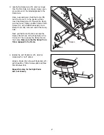
Page 7: ...en erous amount of the included grease to the Ramp Axle Have a second person hold the Ramp 78 near the Frame 1 in the position shown Insert the Ramp Axle 74 through the Ramp and the Frame Tighten an M8 x 25mm Patch Screw 70 with an M8 Washer 64 and a Ramp Cover 59 into each end of the Ramp Axle Next pull the Ramp Pin 90 and align the Ramp 78 with one of the three holes in the Frame 1 Then release ...

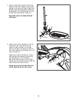
Page 8: ...an M8 x 25mm Patch Screw 70 with an M8 Washer 64 and a Pedal Leg Cover 23 into the end of the Left Crank Arm 42 Repeat this step for the Right Pedal Arm and the Right Crank Arm not shown 6 70 42 21 45 20 23 64 Grease 5 Orient an Upper Body Leg 6 and a Ramp Wheel 24 as shown Apply a small amount of grease to the barrel of an M8 x 63mm Bolt Set 67 Attach the Upper Body Leg and the Ramp Wheel to the ...

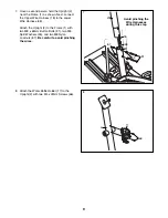
Page 9: ...ear the Frame 1 as shown Next connect the Upper Wire Harness 18 to the Lower Wire Harness 38 Attach the Upright 2 to the Frame 1 with two M8 x 69mm Button Bolts 91 two M8 Split Washers 93 and two M8 Nylon Locknuts 87 Be careful to avoid pinching the wires 2 38 18 1 93 2 17 66 91 Avoid pinching the Wire Harnesses during this step 87 ...

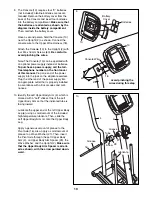
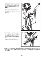
Page 10: ...nto the jack on the elliptical exerciser Plug the other end of the power supply into an appropriate outlet that is properly installed in accordance with all local codes and ordi nances 10 Identify the Left Upper Body Arm 4 which is marked with a Left sticker Orient the Left Upper Body Arm so that the indicated tube is facing inward Lubricate the upper end of the left Upper Body Leg 6 using a small...

Page 11: ...all amount of grease to each end of the Pivot Axle 16 Slide an M8 Large Washer 81 onto an M8 x 25mm Patch Screw 70 and tighten the Patch Screw into the left end of the Pivot Axle Then press a Pivot Cover 14 against the Left Upper Body Arm 4 Repeat this step on the right side of the elliptical exerciser 11 12 13 Make sure that all parts of the elliptical exerciser are properly tightened Note Some h...

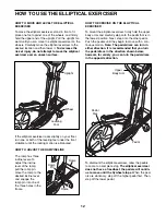
Page 12: ...ll the ramp pin move the ramp to the desired incline level and engage the ramp pin into one of the three holes in the frame HOW TO EXERCISE ON THE ELLIPTICAL EXERCISER To mount the elliptical exerciser firmly hold the upper body arms and carefully step onto the pedal that is in the lowest position Next step onto the other pedal Push the pedals until they begin to move with a con tinuous motion Not...

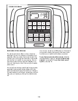
Page 13: ...e console also features eight target toning programs designed to work specific muscle groups Each pro gram automatically changes the resistance of the ped als and prompts you to increase or decrease your ped aling pace as it guides you through an effective work out You can also connect your MP3 player or CD player to the console s stereo sound system and listen to your favorite music or audio book...

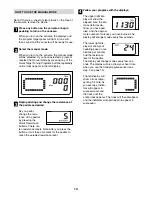
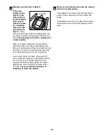
Page 14: ...stance buttons There are ten resistance levels Note After you press the buttons it will take a moment for the pedals to reach the selected resistance level Follow your progress with the displays The upper right dis play will show the elapsed time the dis tance total revolu tions you have ped aled and the approxi mate number of calories you have burned The display will change modes every few second...

Page 15: ...ate will be shown For the most accurate heart rate read ing hold the contacts for at least 15 seconds If your heart rate is not shown make sure that your hands are positioned as described Be care ful not to move your hands excessively or to squeeze the metal contacts tightly For optimal performance clean the metal contacts using a soft cloth never use alcohol abrasives or chemicals to clean the co...

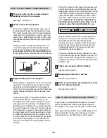
Page 16: ...level will appear in the lower right display for a few seconds to alert you The resistance of the pedals will then change During the program the program target pacer will prompt you to keep your pedaling pace near the target pace setting for the current segment When a left indicator lights increase your pace when a right indicator lights decrease your pace When the center indicator lights maintain...

Page 17: ...elliptical exerciser in a clean dry location away from moisture and dust CONSOLE TROUBLESHOOTING If the console does not function properly the batteries should be replaced To replace the batteries see assembly step 9 on page 9 HANDGRIP PULSE SENSOR TROUBLESHOOTING If the handgrip pulse sensor does not function proper ly make sure that your hands are positioned as described in step 5 on page 15 Be ...

Page 18: ... exercise must be aerobic Aerobic exercise is activity that requires large amounts of oxygen for prolonged periods of time This increases the demand on the heart to pump blood to the muscles and on the lungs to oxygenate the blood For aerobic exercise adjust the intensity of your exercise until your heart rate is near the highest number in your training zone WORKOUT GUIDELINES Each workout should ...

Page 19: ...illes Stretch With one leg in front of the other reach forward and place your hands against a wall Keep your back leg straight and your back foot flat on the floor Bend your front leg lean forward and move your hips toward the wall Hold for 15 counts then relax Repeat 3 times for each leg To cause further stretching of the achilles tendons bend your back leg as well Stretches Calves achilles tendo...

Page 20: ...20 NOTES ...

Page 21: ... 41 2 Crank Snap Ring 42 1 Left Crank Arm 43 1 Right Crank Arm 44 1 Resistance Cable 45 2 Crank Arm Spacer 46 1 Clamp 47 1 Reed Switch Wire 48 1 Flywheel 49 1 Flywheel Axle 50 2 Flywheel Bearing 51 1 C Magnet 52 1 C Magnet Bracket 53 1 Magnet 54 1 Spring 55 1 Idler 56 1 Resistance Motor 57 2 Flange Screw 58 4 M10 x 77mm Carriage Bolt 59 4 Ramp Cover 60 13 M4 x 16mm Screw 61 1 M8 x 19mm Flat Head B...

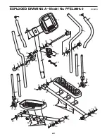
Page 22: ...81 70 8 9 17 66 7 5 18 70 81 15 14 15 24 19 6 68 21 25 64 70 25 68 26 22 19 64 70 4 27 27 20 20 85 85 85 85 11 15 23 23 25 25 7 6 29 28 67 24 26 26 26 28 29 94 94 11 11 11 92 92 67 67 67 EXPLODED DRAWING A Model No PFEL3906 0 R0807B ...

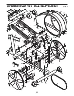
Page 23: ...7 48 46 60 47 49 53 50 50 87 64 64 51 54 65 83 63 76 77 84 60 60 30 60 3 60 60 80 60 31 60 34 55 56 44 52 75 75 75 75 75 75 69 82 82 12 12 70 64 64 70 58 84 84 84 73 79 74 78 59 59 73 59 59 73 79 87 91 86 86 36 88 89 88 89 90 93 93 13 13 72 EXPLODED DRAWING B Model No PFEL3906 0 R0807B 23 ...

Page 24: ...arranty does not extend to any product or damage to a product caused by or attributable to freight damage abuse misuse improper or abnormal usage or repairs not provided by an ICON authorized service center products used for commercial or rental purposes or products used as store display models No other warranty beyond that specifically set forth above is authorized by ICON ICON is not responsible...

Reviews: