background image

19

Inspect and properly tighten all parts of the elliptical

trainer regularly. Replace any worn parts immediately.

The elliptical trainer can be cleaned with a soft cloth

and a small amount of mild detergent.

Do not use

abrasives or solvents.

To prevent damage to the

console, keep liquids away from the console and keep

the console out of direct sunlight.

When storing the elliptical trainer, remove the batter-

ies from the console. Keep the elliptical trainer in a

clean, dry location, away from moisture and dust.

CONSOLE TROUBLESHOOTING

If the console does not function properly, replace the

batteries (see assembly step 3 on page 6).

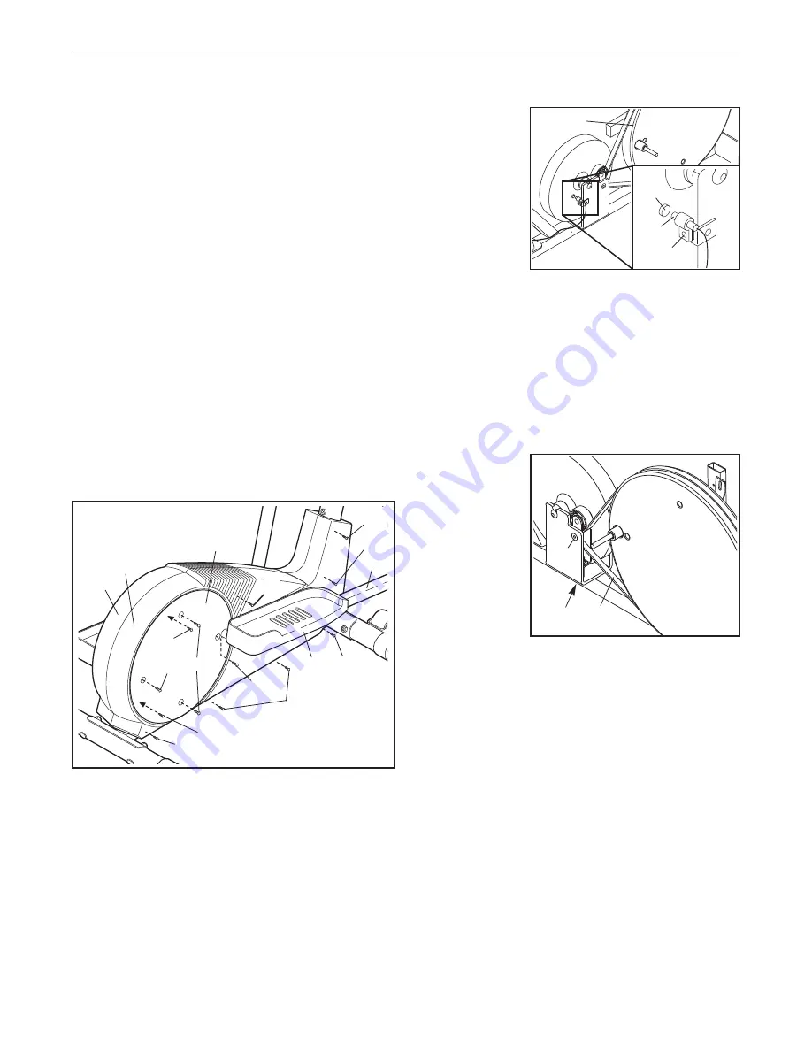
HOW TO ADJUST THE REED SWITCH

If the console does not display correct feedback, the

reed switch should be adjusted. To adjust the reed

switch, first see assembly step 9 on page 8 and

remove the Pedals (13, 14). Next, see step 8 on page

8 and remove the Pedal Arms (11, 12).

Next, remove the four Screws (51, 72) from the right

Pedal Disc (15), and slide the Pedal Disc off. Remove

all Screws (71, 64) from the Right Side Shield (4), and

remove the Right Side Shield. Remove all Screws

(52) from the Left Side Shield (3) and remove the Left

Side Shield.

Next, locate

the Reed

Switch (53).

Loosen, but

do not

remove, the

indicated

Screw (52).

Slide the

Reed Switch

slightly toward

or away from

the Magnet (58) on the flywheel. Retighten the Screw.

Turn the left Pedal Disc (15) for a moment. Repeat

until the console displays correct feedback.
When the Reed Switch (53) is correctly adjusted, reat-

tach the Side Shields (3, 4), the right Pedal Disc (15),

the Pedal Arms (11, 12), and the Pedals (13, 14).

HOW TO ADJUST THE DRIVE BELT

If you can feel

the pedals slip

whilst you are

pedaling, even

when the resis-

tance is adjust-

ed to the maxi-

mum level, the

Drive Belt (19)

may need to

be adjusted. To

adjust the

Drive Belt, you

must remove both side shields. See the instructions at

the left and remove the side shields.

Next, loosen the M8 x 22mm Flat Head Screw (26)

and turn the M10 x 60mm Screw (62) until the Drive

Belt (19) is tight. Once the Drive Belt is tight, tighten

the Flat Head Screw. Reattach the side shields.

MAINTENANCE AND TROUBLESHOOTING

64

71

72

51

71

52

51

52

64

64

14

12

4

58

53

52

15

15

3

26

62 19

64

Summary of Contents for 565 Ekg Elliptical

Page 1: ...www iconeurope com Visit our website at QUESTIONS As a manufacturer we are committed to providing com plete customer satisfaction If you have questions or if there are missing parts please call Or wri...

Page 2: ...RE YOU BEGIN 4 ASSEMBLY 5 HOW TO USE THE ELLIPTICAL TRAINER 9 MAINTENANCE AND TROUBLESHOOTING 19 CONDITIONING GUIDELINES 20 PART LIST 22 EXPLODED DRAWING 23 HOW TO ORDER REPLACEMENT PARTS Back Cover P...

Page 3: ...ath letic shoes for foot protection 9 Always hold the pulse sensor or the handle bars when mounting dismounting or using the elliptical trainer 10 The pulse sensor is not a medical device Various fac...

Page 4: ...tment at 08457 089 009 To help us assist you please note the product model number and serial number before calling The model number is PFEVEL39831 The serial number can be found on a decal attached to...

Page 5: ...6 6 M4 x 22mm Screw 42 2 Pedal Arm Bolt Set 40 2 M8 x 45mm Button Bolt 50 4 M10 x 75mm Carriage Bolt 34 4 M10 x 76mm Button Bolt 27 2 M8 5 Washer 55 2 M10 Split Washer 59 2 M10 Nylon Locknut 33 6 M8 N...

Page 6: ...ne batteries are recommended Remove the Screw 72 from the battery drawer Pull the battery drawer open and insert four batteries into the battery drawer Make sure that the batteries are oriented as sho...

Page 7: ...not get pinched and damaged during this step 6 Identify the Left Handlebar 6 which is marked with a sticker Insert the Left Handlebar into one of the Handlebar Arms 5 make sure that the Handlebar Arm...

Page 8: ...lide a Handlebar Spacer 47 onto the short tube on each Handlebar 6 8 and rotate the Handlebar Spacers so the arrows are pointing toward the floor Next slide the Handlebars onto the Pivot Axle 73 Make...

Page 9: ...p onto the other pedal Push the pedals until they begin to move with a continuous motion Note The pedal disks can turn in either direction It is recommended that you turn the pedal disks in the direct...

Page 10: ...included audio cable you can connect the elliptical trainer to your home stereo portable stereo computer or VCR and play special iFIT com CD and video programs iFIT com CDs and videocassettes are avai...

Page 11: ...w only the distance you have pedaled or the number of calories or fat calories you have burned press the upper button on the left side of the large display until only the word DISTANCE CALORIES or FAT...

Page 12: ...o dashes will appear and then your heart rate will be shown For the most accurate heart rate reading continue to hold the handgrips for about 30 seconds Note When you first hold the handgrips the larg...

Page 13: ...tance of the pedals will automatically change if a different resistance level is programmed for the next period The target pace for the current period will be shown by the arrows in the small display...

Page 14: ...he PHONES jack on your CD player Plug your head phones into the other side of the splitter HOW TO CONNECT YOUR PORTABLE STEREO Note If your stereo has an RCA type AUDIO OUT jack see instruction A belo...

Page 15: ...used side of the Y adapter Plug the Y adapter into the LINE OUT jack on your stereo HOW TO CONNECT YOUR COMPUTER Note If your computer has a 3 5mm LINE OUT jack see instruction A If your computer has...

Page 16: ...e adapter into the AUDIO OUT jack on your VCR B Plug one end of the audio cable into the jack beneath the console Plug the other end of the audio cable into the adapter Plug the adapter into an RCA Y...

Page 17: ...ayer or VCR A moment after the play button is pressed your personal trainer will begin guiding you through your workout Simply follow your personal trainer s instructions The program will function in...

Page 18: ...l display Go to your computer and start an internet con nection Start your Web browser if necessary and go to our Web site at www iFIT com Follow the desired links on our Web site to select a program...

Page 19: ...move all Screws 71 64 from the Right Side Shield 4 and remove the Right Side Shield Remove all Screws 52 from the Left Side Shield 3 and remove the Left Side Shield Next locate the Reed Switch 53 Loos...

Page 20: ...exercise Aerobic Exercise If your goal is to strengthen your cardiovascular sys tem your exercise must be aerobic Aerobic exer cise is activity that requires large amounts of oxygen for prolonged per...

Page 21: ...lles Stretch With one leg in front of the other reach forward and place your hands against a wall Keep your back leg straight and your back foot flat on the floor Bend your front leg lean forward and...

Page 22: ...7 M10 Nylon Locknut 34 4 M10 x 75mm Carriage Bolt 35 2 M8 5 LargeWasher 36 6 M4 x 19mm Flange Screw 37 4 Pedal Arm Bushing 38 7 M8 Nylon Locknut 39 1 Large Flywheel Washer 40 2 Pedal Arm Bolt Set 41...

Page 23: ...3 21 68 39 60 60 40 40 14 12 35 37 38 37 36 36 72 51 72 51 15 52 18 19 20 20 34 9 33 33 16 61 61 16 62 1 30 31 31 32 30 38 7 33 51 51 72 15 13 37 36 38 35 11 40 40 71 64 52 33 26 59 59 58 52 54 52 53...

Page 24: ...Industrial Estate Revie Road Beeston Leeds LS118JG UK Tel Outside the UK 0 044 113 387 7133 Fax 0 044 113 387 7125 To help us assist you please be prepared to give the following information the MODEL...

Reviews: