background image

8

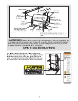
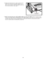
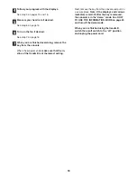
4. Insert the Console Wire Harness (78) and the TV cable

into the Uprights (84).

Set the console assembly on the Uprights (84). 

Be care-

ful to avoid pinching the Console Wire Harness (78)
and the TV cable. 

While a second person holds the con-

sole assembly, attach it with four Console Bolts (64) and
four Star Washers (8) as shown; 

start all four Console

Bolts and then firmly tighten them.

Console

Assembly

64

78

64

8

8

TV Cable

84

84

4

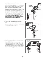
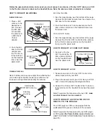
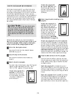
2. With the help of a second person, carefully raise the

Uprights (84) to a vertical position. 

Have the second person hold the console assembly near
the Uprights (84) as shown. Look under the console as-
sembly and locate the Console Wire Harness (78). 

Remove the tie securing the Upright Wire Harness (77) to
the right Upright (84). Next, connect the Upright Wire
Harness to the Console Wire Harness (78).

Make sure to

connect the connectors properly (see the inset draw-
ing). The connectors should slide together easily and
snap into place.

If the connectors do not slide together

easily and snap into place, turn one connector and then
try again. 

IF THE CONNECTORS ARE NOT CON-

NECTED PROPERLY, THE CONSOLE MAY BE DAM-
AGED WHEN THE POWER IS TURNED ON.

84

77

78

2

Console

Assembly

77

78

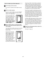
3. Look under the console assembly and locate the TV

cable. 

Remove the tie securing the Upright TV Cable (104) to
the left Upright (84). Connect the Upright TV Cable to the
TV cable on the console assembly. 

84

104

TV Cable

Console

Assembly

3

Summary of Contents for 585 Perspective

Page 1: ... you have questions or if any parts are missing or damaged PLEASE CONTACT OUR CUS TOMER SERVICE DEPARTMENT DIRECTLY Call toll free 800 830 7240 E mail service goodfamily cc Goodfamily s Web site www goodfamily cc ICON s Web site www iconfitness com Goodfamily is an authorized dealer of this treadmill in the territory of mainland China This treadmill is designed and manufactured by ICON Health Fitn...

Page 2: ...7 HOW TO USE THE CHEST PULSE SENSOR 12 OPERATION AND ADJUSTMENT 13 HOW TO FOLD AND MOVE THE TREADMILL 26 TROUBLESHOOTING 27 CONDITIONING GUIDELINES 30 PART LIST 31 EXPLODED DRAWING 32 ORDERING REPLACEMENT PARTS Back Cover PROFORM is a registered trademark of ICON IP Inc 2 ...

Page 3: ...he power cord away from heated sur faces 13 Never move the walking belt while the power is turned off Do not operate the treadmill if the power cord or plug is damaged or if the treadmill is not working properly See TROU BLESHOOTING on page 27 if the treadmill is not working properly 14 Read understand and test the emergency stop procedure before using the treadmill see HOW TO TURN ON THE POWER on...

Page 4: ...t be lo cated in the vicinity of overhead power lines or other electric light or power circuits or where it can fall into such power lines or cir cuits When installing an outside antenna sys tem extreme care should be taken to keep from touching such power lines or circuits as contact with them might be fatal 27 To reduce the risk of electric shock do not re move the cover or the back of the telev...

Page 5: ...ns with pre existing health problems Read all instructions before using ICON assumes no responsibility for personal injury or property damage sustained by or through the use of this product SAVE THESE INSTRUCTIONS Power Lines Ground Clamps Ground Clamps Ground Clamp Bonding Jumper Standoff Insulators Antenna Lead in Wire Ground Wire Ground Wire Antenna Discharge Unit To External Antenna Terminal o...

Page 6: ...ual please see the front cover of this man ual To help us assist you please note the product model number and serial number before contacting us The model number of the treadmill is PATL41306 0 The serial number can be found on a decal attached to the treadmill see the front cover of this manual for the location Before reading further please familiarize yourself with the parts that are labeled in ...

Page 7: ... do not use power tools for assembly 1 Make sure that the power cord is unplugged With the help of a second person carefully tip the treadmill onto its left side as shown Partially fold the Frame 58 so the treadmill is more stable Do not fully fold the treadmill until it is completely assembled Attach four Base Pads 82 only two are shown to the base of the Uprights 84 with four 1 Tek Screws 22 Ins...

Page 8: ...onsole as sembly and locate the Console Wire Harness 78 Remove the tie securing the Upright Wire Harness 77 to the right Upright 84 Next connect the Upright Wire Harness to the Console Wire Harness 78 Make sure to connect the connectors properly see the inset draw ing The connectors should slide together easily and snap into place If the connectors do not slide together easily and snap into place ...

Page 9: ...the ball on the bracket is aligned with end of the Shock 92 Then press the end of the Shock onto the ball Note It may be necessary to press the end of the Shock onto the ball while the Frame is moving See drawing 7a Insert the Shock Pin 25 into the two in dicated small holes in the end of the Shock 92 Then rotate the Shock Pin until it clips onto the Shock Note Extra Shock Pins are included Press ...

Page 10: ... mat under the tread mill Note Extra hardware may be included Keep the included allen wrench in a secure place the allen wrench is used to adjust the walking belt see page 28 8 Note the location of the 75 ohm antenna terminal on the treadmill For the television to operate properly an an tenna a CATV cable or a VCR must be connected to the 75 ohm antenna terminal see page 11 75 Ohm Antenna Terminal...

Page 11: ...al on the treadmill frame near the power cord HOW TO CONNECT A VCR 1 Connect one end of a 75 ohm CATV cable to the video output jack on your VCR 2 Plug in the power cord of your VCR See your VCR user s manual for proper grounding instructions 3 Connect the 75 ohm CATV cable to the 75 ohm an tenna terminal on the treadmill frame near the power cord Note To operate the television with your VCR make ...

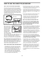
Page 12: ...tic bag or other container that may trap moisture Do not expose the chest pulse sensor to direct sun light for extended periods of time do not expose it to temperatures above 50 C 120 F or below 10 C 15 F Do not excessively bend or stretch the sensor unit when using or storing the chest pulse sensor Clean the sensor unit using a damp cloth never use alcohol abrasives or chemicals The chest strap m...

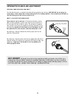
Page 13: ...ug Important If the power cord is damaged it must be replaced with a manufacturer recommended power cord See drawing 1 Plug the indicated end of the power cord into the socket on the treadmill See drawing 2 Plug the power cord into an appropriate outlet that is properly installed and earthed in accordance with all local codes and ordinances Important The treadmill is not compatible with GFCI equip...

Page 14: ...ctive Workout system The iFIT system enables the console to accept iFIT Interactive Workout Cards containing workout programs designed to help you achieve spe cific fitness goals For example lose unwanted pounds or train for a long distance run iFIT programs automat ically control the treadmill while the voice of a personal trainer coaches you and motivates you through every step of your workout i...

Page 15: ...d by pressing the Speed in crease and decrease buttons Each time a button is pressed the speed setting will change by 0 1 Km H if a button is held down the speed setting will change in increments of 0 5 Km H Note After the buttons are pressed it may take a moment for the walking belt to reach the selected speed setting If one of the numbered Speed buttons is pressed the walking belt will gradually...

Page 16: ...ext hold the handgrip pulse sensor with your palms resting on the metal contacts avoid mov ing your hands When your pulse is detected the heart shaped indicator in the right display will flash each time your heart beats one or two dashes will appear and then your heart rate will be shown For the most accurate heart rate reading continue to hold the contacts for about 15 seconds Turn on the fan if ...

Page 17: ...the first segment ends all speed settings in the matrix will move one column to the left The speed setting for the second segment will then be shown in the flashing Current Segment column and the treadmill will automatically adjust to the speed and incline set tings for the second segment Note If all of the in dicators in the Current Segment column are lit after the speed settings have moved to th...

Page 18: ...rogram ends make sure that the in cline of the treadmill is at the lowest setting Next remove the key from the console and put it in a secure place Note If the displays and various indicators remain lit after the key is removed the console is in the demo mode See HOW TO USE THE INFORMATION MODE on page 24 and turn off the demo mode When you are finished using the treadmill switch the on off switch...

Page 19: ...r in the right dis play and the target heart rate setting for the program will begin to flash If desired change the target heart rate setting by pressing the in crease or decrease button below the matrix see EXER CISE INTENSITY on page 30 If heart rate program 22 23 or 24 is selected the word PULSE will appear in the right display and the maximum target heart rate setting of the program will begin...

Page 20: ...bring your heart rate closer to the target heart rate set ting If the speed or incline setting is too high or too low at any time during the program you can adjust the setting with the Speed or Incline buttons However when the console compares your heart rate to the target heart rate setting the speed of the treadmill may automatically change to bring your heart rate closer to the target heart rat...

Page 21: ...et tings are not shown in the matrix To program a speed setting and an incline setting for the first segment simply adjust the speed and incline of the treadmill as desired by pressing the Speed and Incline buttons Every few times a Speed but ton is pressed an additional indicator will appear or disappear in the Current Segment column When the first segment of the program ends the current speed se...

Page 22: ...ash a se ries of tones will sound the speed setting and the incline setting will flash in the right display and all speed settings will move one column to the left The speed setting for the second segment will then be shown in the flashing Current Segment column and the treadmill will automatically adjust to the second speed and incline settings that you pro grammed previously The program will con...

Page 23: ...and incline settings of the program Hold the handrails and begin walking During the program a personal trainer will guide you through the workout If desired adjust the vol ume by pressing the Volume buttons or select an audio setting for your personal trainer see HOW TO USE THE INFORMATION MODE on page 24 If the speed or incline setting for the current seg ment is too high or too low you can manua...

Page 24: ...e HOW TO USE THE INFORMATION MODE The console features an information mode that allows you to view treadmill usage information select a sys tem of measurement for the console and turn on and turn off the demo mode The information mode also al lows you to adjust the settings of the television and to save channels into the television s memory Follow the steps below to use the information mode Hold d...

Page 25: ...r the Volume decrease button to delete the channel Continue this process until you have added all desired channels and deleted all unwanted channels Press the On Off button again and select a video broadcast system for a single channel To select a video broadcast system for a single channel first press the Channel buttons until the desired channel number appears on the screen Then press the Volume...

Page 26: ...ve the treadmill in the storage position in temperatures above 30 Celsius 85 Fahrenheit HOW TO MOVE THE TREADMILL Before moving the treadmill convert the treadmill to the storage position as described above Make sure that the catch is se curely held by the latch pin 1 Hold the upper ends of the handrails Place one foot against one of the wheels 2 Tilt the treadmill back until it rolls freely on th...

Page 27: ... the treadmill frame near the power cord see the drawing above If the circuit breaker has tripped wait for five minutes and then press the switch back in b Make sure that the power cord is plugged in If the power cord is plugged in unplug it wait for five minutes and then plug it back in c Remove the key from the console Reinsert the key into the console d Make sure that the on off switch is in th...

Page 28: ... plug in the power cord insert the key and run the treadmill for a few minutes Repeat until the walking belt is properly tightened c If the walking belt still slows when walked on see the front cover of this manual PROBLEM The walking belt is off center or slips when walked on SOLUTION a If the walking belt is off center first remove the key and UNPLUG THE POWER CORD If the walking belt has shifte...

Page 29: ...ge area of a television station where the signal is weak the picture may be of poor quality or a blue screen may appear If the signal is weak it may be necessary to install an external antenna to improve the picture Note If one of these symptoms appears when the cable from a CATV company is connected the symptom may be caused by the local company broadcast PROBLEM The chest pulse sensor does not f...

Page 30: ...y that requires large amounts of oxygen for prolonged periods of time This increases the demand on the heart to pump blood to the muscles and on the lungs to oxygenate the blood For aerobic exercise adjust the speed and incline of the treadmill until your heart rate is near the highest number in your training zone WORKOUT GUIDELINES Each workout should include the following three parts A Warm up S...

Page 31: ... Frame 59 1 Belly Pan 60 1 Reed Switch Bracket 61 1 Reed Switch Clip 62 1 Front Roller Nut 63 1 Reed Switch 64 4 Console Bolt 65 4 Extension Leg Bolt 66 4 Star Washer 67 4 Extension Leg Nut 68 2 Caution Decal 69 1 Warning Decal 70 2 Platform Nut 71 11 Cable Tie 72 1 Cotter Pin Bottom 73 1 Latch Housing 74 2 Tie Clamp 75 1 Releasable Tie 76 1 Access Door 77 1 Upright Wire Harness 78 1 Console Wire ...

Page 32: ...9 12 11 15 10 46 47 10 49 48 9 58 51 53 40 52 54 33 57 53 12 15 55 70 70 11 69 5 5 5 83 83 93 94 1 1 94 5 5 90 90 93 91 6 3 6 3 40 17 91 116 5 5 7 7 4 3 116 32 EXPLODED DRAWING A Model No PATL41306 0 R0906A ...

Page 33: ...27 26 42 24 33 36 101 95 102 98 97 96 100 18 104 105 63 2 3 59 60 83 2 33 61 83 83 2 2 2 3 41 50 103 103 103 103 103 83 3 33 66 33 38 33 39 108 66 33 106 110 40 30 115 117 118 33 EXPLODED DRAWING B Model No PATL41306 0 R0906A ...

Page 34: ...2 68 68 72 87 86 88 56 18 18 65 8 8 65 31 32 3 44 3 44 31 32 8 8 64 64 8 64 8 21 64 20 92 25 33 77 81 32 80 67 82 89 81 32 80 67 82 22 89 82 22 82 22 87 104 73 3 22 99 34 EXPLODED DRAWING C Model No PATL41306 0 R0906A ...

Page 35: ...3 76 79 75 33 74 71 37 35 35 3 3 14 13 3 3 3 3 3 3 3 3 3 3 85 34 78 33 23 19 109 29 112 111 119 107 114 35 EXPLODED DRAWING D Model No PATL41306 0 R0906A ...

Page 36: ... by Goodfamily Goodfamily is not responsible or liable for indirect special or consequential damages arising out of or in connection with the use or performance of the product or damages with respect to any economic loss loss of property loss of revenues or profits loss of enjoyment or use costs of removal or installation or other consequential damages of whatsoever nature Some states do not allow...

Reviews: