background image

9

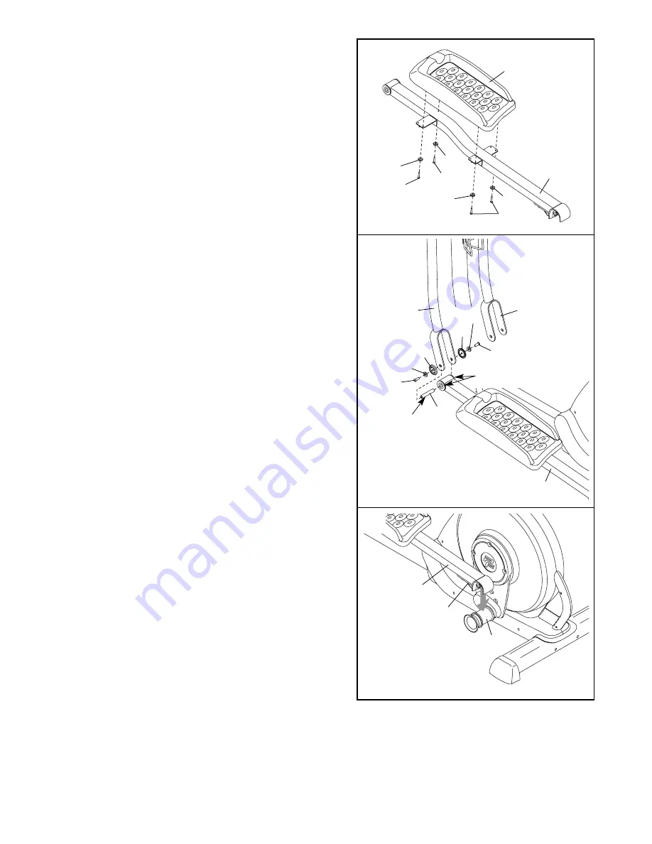
13. Apply a thin film of grease to one of the Pedal Leg

Axles (32) and to the faces of the two Pedal Leg
Bushings (33) in the Left Pedal Leg (14). 

Next, slide an M8 Washer (88) and a Pedal Leg Cover
(31) onto an M8 x 23mm Shoulder Screw (115), and
turn the Shoulder Screw a few turns into the Pedal
Leg Axle (32).

While another person holds the front end of the Left
Pedal Leg (14) inside of the bracket on the Left Upper
Body Arm (11), insert the Pedal Leg Axle (32) into
both parts. Next, slide an M8 Washer (88) and a
Pedal Leg Cover (31) onto another M8 x 23mm
Shoulder Screw (115), and turn the Shoulder Screw a
few turns into the Pedal Leg Axle. Tighten both
Shoulder Screws.

Repeat this step on the other side of the elliptical
exerciser.

14. Lift the latch on the underside of the Left Pedal Leg

(14), and set the Left Pedal Leg on the left Crank
Bushing Sleeve (43). Release the lever, and make sure
that the Left Pedal Leg is securely connected to the
Crank Bushing Sleeve.

Connect the Right Pedal Leg (not shown) in the same
way. 

See step 5.

Tighten the M8 x 69mm Button Bolt (80)

and the two M8 x 23mm Button Screws (84). 

12. Identify the Left Pedal (13) and the Left Pedal

Leg (14), which are marked with stickers. 

Attach the Left Pedal (13) to the Left Pedal Leg (14)
with an M4 x 45mm Screw (108), three M4 x 14mm
Screws (104), and four Star Washers (112).

Attach the Right Pedal (not shown) to the Right
Pedal Leg (not shown) in the same way.

15.

Make sure that all parts of the elliptical exerciser are properly tightened.

Note: Some hardware may be

left over after assembly is completed. To protect the floor or carpet from damage, place a mat under the
elliptical exerciser.

Grease

13

115

32

88

31

12

11

14

Latch

14

43

13

14

104

104

112

112

112

112

14

108

12

115

88

33–Grease

31

Summary of Contents for 600 N Elliptical

Page 1: ...TIONS As a manufacturer we are com mitted to providing complete customer satisfaction If you have questions or if parts are damaged or missing PLEASE CONTACT OUR CUSTOMER SERVICE DEPARTMENT DIRECTLY CALL TOLL FREE 1 888 533 1333 Mon Fri 6 a m 6 p m MST ON THE WEB www proformservice com Visit our website at www proform com new products prizes fitness tips and much more USER S MANUAL ...

Page 2: ...SSEMBLY 5 HOW TO USE THE ELLIPTICAL EXERCISER 10 MAINTENANCE AND TROUBLESHOOTING 18 CONDITIONING GUIDELINES 19 PART LIST 20 EXPLODED DRAWING 22 HOW TO ORDER REPLACEMENT PARTS Back Cover LIMITED WARRANTY Back Cover 2 PROFORM is a registered trademark of ICON IP Inc ...

Page 3: ...weighing more than 250 pounds 8 Wear appropriate exercise clothes while using the elliptical exerciser Always wear athletic shoes for foot protection while exer cising 9 Hold the handgrip pulse sensor or the han dlebars when mounting dismounting or using the elliptical exerciser 10 The pulse sensor is not a medical device Various factors may affect the accuracy of heart rate readings The pulse sen...

Page 4: ...ease note the product model number and serial number before con tacting us The model number is PFEL6026 0 The serial number can be found on a decal attached to the elliptical exerciser see the front cover of this manual for the location of the decal To avoid a registration fee for any service needed under warranty you must register the elliptical exerciser at www proformservice com registration Be...

Page 5: ...entheses below each drawing is the key number of the part from the PART LIST on pages 20 and 21 The number follow ing the parentheses is the quantity needed for assembly Note Some small parts may have been pre assem bled If a part is not in the parts bag check to see if it has been pre assembled M10 x 127mm Button Screw 83 2 M4 x 14mm Screw 104 8 M8 Jamnut 79 5 M8 Washer 88 6 Wave Washer 111 2 M8 ...

Page 6: ...the Left Crank Arm 36 which is marked with a sticker Hold the Left Crank Arm against the left Crank Hub 38 and align the holes in the Left Crank Arm with the unused holes in the Crank Hub Next insert four Hub Screws 87 into the Left Crank Arm and finger tighten the Hub Screws into the Crank Hub Tighten one of the Hub Screws and then tighten the Hub Screw farthest from the first Hub Screw Then tigh...

Page 7: ... two tabs on the battery cover and remove the bat tery cover Next insert four batteries into the Console Make sure that the batteries are oriented as shown by the diagrams inside of the battery compart ments Then reattach the battery cover to the Console 5 While another person holds the Upright 3 connect the Upper Wire Harness 48 to the Lower Wire Harness 49 Gently pull the upper end of the Upper ...

Page 8: ...t end of the Pivot Axle Tighten an M8 x 23mm Button Screw 84 with an M8 Washer 88 and a Wave Washer 111 into each end of the Pivot Axle 74 Make sure that the Wave Washers are on the ends of the Pivot Axle 9 Identify the Left Handlebar 8 and the Left Upper Body Arm 11 which are marked with stickers Orient the Left Handlebar 8 and the Left Upper Body Arm 11 as shown Insert the Left Handlebar into th...

Page 9: ...t Pedal Leg 14 and set the Left Pedal Leg on the left Crank Bushing Sleeve 43 Release the lever and make sure that the Left Pedal Leg is securely connected to the Crank Bushing Sleeve Connect the Right Pedal Leg not shown in the same way See step 5 Tighten the M8 x 69mm Button Bolt 80 and the two M8 x 23mm Button Screws 84 12 Identify the Left Pedal 13 and the Left Pedal Leg 14 which are marked wi...

Page 10: ...e pedal legs on the sleeves on the crank arms Release the latches and make sure that the pedal legs are securely connected to the crank arms HOW TO MOVE THE ELLIPTICAL EXERCISER To move the elliptical exerciser first fold it as described at the left Next stand in front of the ellipti cal exerciser hold the handle on the console bracket and place one foot against the center of the front sta bilizer...

Page 11: ...free wheel the pedals will continue to move until the flywheel stops When the pedals are stationary step off the highest pedal first Then step off the lowest pedal HOW TO ADJUST THE STRIDE OF THE ELLIPTICAL EXERCISER To adjust the stride of the elliptical exerciser first pull one of the adjustment knobs until the adjustment bracket can be pivoted freely Pivot the adjustment bracket until the adjus...

Page 12: ...sistance rpm programs Each pulse control program automatically controls the resistance of the pedals and prompts you to increase or decrease your pedaling pace to keep your heart rate near a target heart rate setting during your workout Each resistance rpm program automatically changes the resistance of the pedals and prompts you to vary your pedaling pace as it guides you through an effective wor...

Page 13: ...t side of the display will show the elapsed time and the approximate number of calories you have burned Note When a preset program is selected except for pulse program 2 the display will show the time remaining in the program instead of the elapsed time The left side of the display will also show your heart rate when you use the handgrip pulse sen sor see step 5 on page 14 The center of the displa...

Page 14: ...f your heart rate is not shown make sure that your hands are positioned as described Be care ful not to move your hands excessively or to squeeze the metal contacts too tightly For opti mal performance clean the metal contacts using a soft cloth never use alcohol abrasives or chemicals Turn on the fan if desired To turn on the fan at low speed press the Fan button To turn on the fan at high speed ...

Page 15: ...rate setting see EXERCISE INTENSI TY on page 19 Hold the handgrip pulse sensor It is not necessary to hold the handgrip pulse sensor continuously during a pulse control pro gram however you should hold the handgrip pulse sensor frequently for the program to oper ate properly Each time you hold the handgrip pulse sensor keep your hands on the metal contacts for at least 30 seconds Begin pedaling to...

Page 16: ...ly to provide motivation Your actual heart rate may be slower than the tar get heart rate settings Make sure to exercise at a pace that is comfortable for you Note During the program you can manually over ride the resistance setting for the current seg ment if desired by pressing the increase and decrease buttons However when the console compares your heart rate to the target heart rate setting th...

Page 17: ...tended only to provide motivation Your actual pace may be slower than the pace settings Make sure to exercise at a pace that is comfortable for you When only three seconds remain in the first seg ment of the program both the Current Segment column and the column to the right will flash a series of tones will sound and all resistance set tings will move one column to the left The resis tance settin...

Page 18: ...xes in the center during use turn the base foot until the flexing is eliminated HOW TO LEVEL THE ELLIPTICAL EXERCISER If the elliptical exerciser rocks slightly on your floor during use see HOW TO LEVEL THE ELLIPTICAL EXERCISER on page 10 HANDGRIP PULSE SENSOR TROUBLESHOOTING Avoid moving your hands while using the handgrip pulse sensor Excessive movement may interfere with heart rate readings Do ...

Page 19: ...o strengthen your cardiovascular sys tem your exercise must be aerobic Aerobic exer cise is activity that requires large amounts of oxygen for prolonged periods of time This increases the demand on the heart to pump blood to the muscles and on the lungs to oxygenate the blood For aerobic exercise adjust the intensity of your exercise until your heart rate is near the highest number in your trainin...

Page 20: ... 2 Crank Snap Ring 48 1 Upper Wire Harness 49 1 Lower Wire Harness 50 1 Reed Switch Wire 51 1 Belt 52 1 Flywheel 53 1 C Magnet 54 1 Pillow Block 55 1 Magnet 56 1 Spring 57 1 Idler 58 1 Idler Bracket 59 1 Clamp 60 1 Reed Switch Bracket 61 1 Base Pin 62 2 Latch Bracket Spacer 63 2 Hair Pin 64 1 Latch Bracket 65 1 Pivot Bracket 66 2 Pivot Bracket Spacer 67 1 Frame Pin 68 1 Latch Button 69 1 Roll Pin ...

Page 21: ...justment Spring 107 4 M4 x 12mm Screw 108 2 M4 x 45mm Screw 109 2 Large Snap Ring 110 2 M8 Small Washer 111 2 Wave Washer 112 8 Star Washer 113 1 M10 Washer 114 1 M6 Nut 115 4 M8 x 23mm Shoulder Screw 116 8 M8 x 15mm Button Screw 117 2 Large Wave Washer 118 1 Left Stabilizer Cover 119 1 Right Stabilizer Cover 120 2 M4 x 12mm Round Head Screw 121 2 M8 Large Washer 122 2 Middle Wave Washer 123 1 Rig...

Page 22: ...3 23 25 25 26 30 30 30 30 30 30 31 31 32 33 33 31 33 32 33 31 34 35 35 80 78 101 101 79 105 105 88 84 79 77 77 101 101 84 101 101 74 105 79 78 88 84 104 115 115 104 88 84 104 115 115 104 104 84 88 89 82 81 81 89 48 49 84 73 73 108 88 88 88 88 108 90 90 90 111 111 112 112 112 112 112 101 101 101 118 119 101 101 ...

Page 23: ...3 51 50 57 58 59 60 103 103 85 96 61 62 62 63 64 63 65 66 67 68 69 113 97 70 95 103 79 71 72 107 100 103 103 103 102 102 107 109 123 75 87 114 103 110 53 56 79 110 86 87 87 43 42 42 37 120 120 41 76 106 99 109 116 116 84 84 121 121 122 117 117 122 52 54 55 94 94 94 92 93 91 124 124 EXPLODED DRAWING B Model No PFEL6026 0 R0806A ...

Page 24: ...s warranty does not extend to any product or damage to a product caused by or attributable to freight damage abuse misuse improper or abnormal usage or repairs not provided by an ICON authorized service center products used for commercial or rental purposes or products used as store display models No other warranty beyond that specifically set forth above is authorized by ICON ICON is not responsi...

Reviews: