background image

HOW TO USE THE MANUAL MODE

Insert the key fully into the console.

See HOW TO TURN ON THE POWER on page 10.

Select the manual mode.

When the key is in-
serted, the manual
mode will automatically
be selected and the
manual control indica-
tor will light. If a pro-
gram has been selected, press the PROGRAM
button repeatedly to select the manual mode.

Press the START button or the SPEED 

▲ 

button

to start the walking belt.

A moment after the button is pressed, the walking
belt will begin to move. Hold the handrails and
carefully begin walking. 

As you exercise,
change the speed of
the walking belt as de-
sired by pressing the
SPEED 

▲ 

and 

▼ 

but-

tons. Each time a but-
ton is pressed, the speed will change by 0.1 mph. If
a button is held down, the speed will change in in-
crements of 0.5 mph. To change the speed setting
quickly, press the QUICK SPEED buttons. Note:
After the buttons are pressed, it will take a moment
for the treadmill to reach the selected speed setting.   

To stop the walking belt, press the STOP button.
The TIME/INCLINE/SEG. TIME display will begin
to flash. To restart the walking belt, press the
START button or the SPEED 

button.   

During the first few minutes that you use the tread-
mill, inspect the alignment of the walking belt, and
align the walking belt if necessary (see page 18).

Change the incline of the treadmill as desired.

To change the incline of
the treadmill, press the
INCLINE buttons. Each
time a button is
pressed, the incline will
change by 0.5%. The
buttons can be held down to change the incline
rapidly. Note: After the buttons are pressed, it will
take a moment for the treadmill to reach the se-
lected incline setting. 

Follow your progress with the LED track and
the four displays.

The LED Track
The LED track
represents a dis-
tance of 1/4 mile
(400 m). As you
exercise, the indi-
cators around the
track will light in sequence until you have com-
pleted 1/4 mile. A new lap will then begin. 

DISTANCE/LAPS dis-
play
—This display shows
the distance that you
have walked or run and
the number of laps you
have completed. The dis-
play will alternate between one number and the
other every few seconds, as shown by the arrows
in the display.

TIME/INCLINE/SEG.
TIME display
—When the
manual mode is selected,
this display will show the
elapsed time and the in-
cline level of the treadmill.
Every seven seconds, the display will change
from one number to the other, as shown by the ar-
rows in the display. When a personal trainer pro-
gram is selected, the display will show the time re-
maining 
in the program, the incline level of the
treadmill, and the time remaining in the current seg-
ment of the program.

CALS./FAT CALS./
HEART RATE display

This display shows the
approximate numbers of
calories and fat calories
you have burned (see
FAT BURNING on page
19). Every few seconds, the display will change
from one number to the other, as shown by the ar-
rows in the display. The display will also show
your heart rate when the pulse sensor is used (see
step 6 on page 12).

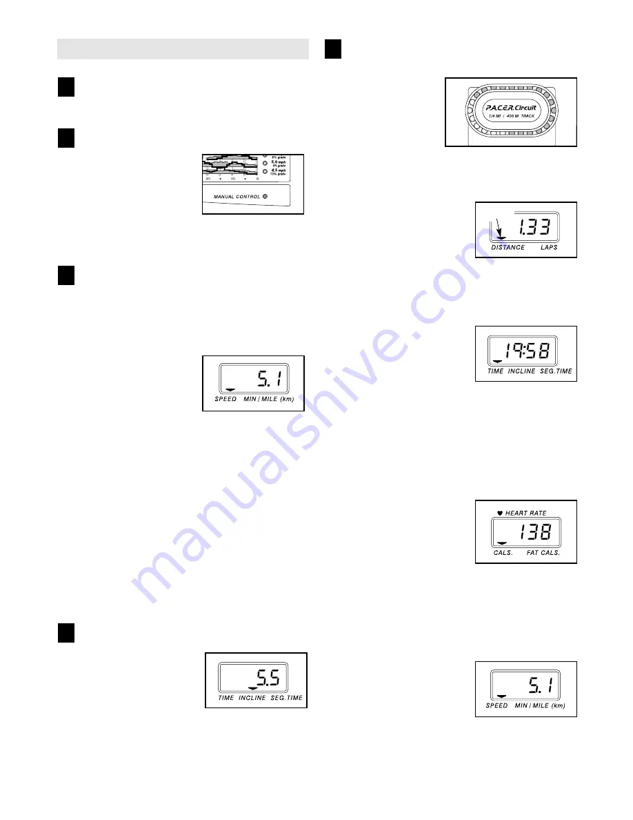
SPEED/MIN-MILE dis-
play
—This display shows
the speed of the walking
belt and your current
pace (pace is measured
in minutes per mile).
Every few seconds, the display will change from
one number to the other, as shown by the arrows
in the display.

5

4

3

2

1

Arrow

Summary of Contents for 625

Page 1: ...u have questions or if there are missing parts we will guar antee complete satisfaction through direct assistance from our factory TO AVOID DELAYS PLEASE CALL DIRECT TO OUR TOLL FREE CUSTOMER HOT LINE The trained technicians on our Customer Hot Line will provide immediate assistance free of charge to you CUSTOMER HOT LINE 1 800 999 3756 Mon Fri 6 a m 6 p m MST Serial Number Decal Find the serial n...

Page 2: ...NT 9 HOW TO FOLD AND MOVE THE TREADMILL 15 TROUBLESHOOTING 17 CONDITIONING GUIDELINES 19 PART LIST 22 ORDERING REPLACEMENT PARTS Back Cover LIMITED WARRANTY Back Cover Note An EXPLODED DRAWING is attached in the center of this manual PROFORM is a registered trademark of ICON Health Fitness Inc 2 ...

Page 3: ...roperly functioning surge suppressor could result in damage to the con trol system of the treadmill If the control sys tem is damaged the walking belt may change speed or stop unexpectedly which may result in a fall and serious injury 13 Keep the power cord and the surge suppres sor away from heated surfaces 14 Never move the walking belt while the power is turned off Do not operate the treadmill ...

Page 4: ...t use this treadmill in any commer cial rental or institutional setting WARNING Before beginning this or any exercise program consult your physician This is especially important for persons over the age of 35 or persons with pre existing health problems Read all instructions before using ICON assumes no responsibility for personal injury or property damage sustained by or through the use of this p...

Page 5: ... free at 1 800 999 3756 Monday through Friday 6 a m until 6 p m Mountain Time ex cluding holidays To help us assist you note the prod uct model number and serial number before calling The model number of the treadmill is PFTL62511 The serial number can be found on a decal attached to the treadmill see the front cover of this manual for the lo cation Before reading further please review the drawing...

Page 6: ...ightly and holds it insert one of the Extension Legs 103 into the treadmill as shown Make sure that the Extension Leg is turned so the Thick Base Pad 97 is on the bottom Next tip the treadmill to the other side and insert the other Extension Leg not shown in the same way Lower the side of the treadmill so that both Extension Legs 103 are resting flat on the floor 2 With the help of a second person...

Page 7: ...post If necessary tap the Handrail Extension with a rubber mallet to fully insert it Next attach the Handrail Extension by tightening three Small Screws 76 into the indicated holes Note If there is only one hole in the top of the post tighten the third Small Screw into the hole in the left side of the post Identify the Left Foam Grip 110 which has a large cutout in the right side Slide the Left Fo...

Page 8: ...e the two Screws 101 the Latch Assembly 9 and the Latch Spacer Reattach the Latch Assembly with the two Screws Make sure that the latch pin engages the Catch 56 9 101 Latch Pin 6 7 Make sure that all parts are properly tightened before you use the treadmill Keep the included allen wrench in a secure place The allen wrench is used to adjust the walking belt see page 18 To protect the floor or carpe...

Page 9: ...rovides a path of least resistance for electric current to reduce the risk of elec tric shock This product is equipped with a cord having an equipment grounding conductor and a grounding plug Plug the power cord into a surge suppressor and plug the surge suppressor into an appropriate outlet that is properly installed and grounded in accordance with all local codes and ordinances Important The tre...

Page 10: ...RN ON THE POWER Plug in the power cord see page 9 Locate the on off switch on the front of the treadmill near the power cord Make sure that the on off switch is in the on position Stand on the foot rails of the treadmill Find the clip attached to the key see the drawing at the top of this page and slide the clip onto the waistband of your clothes Next insert the key into the console After a moment...

Page 11: ...rapidly Note After the buttons are pressed it will take a moment for the treadmill to reach the se lected incline setting Follow your progress with the LED track and the four displays The LED Track The LED track represents a dis tance of 1 4 mile 400 m As you exercise the indi cators around the track will light in sequence until you have com pleted 1 4 mile A new lap will then begin DISTANCE LAPS ...

Page 12: ...er a few seconds your heart rate will be shown Hold your thumbs on the sensor for another 15 seconds for the most accu rate reading If the displayed heart rate appears to be too high or too low or if your heart rate is not displayed lift your thumbs off the sensors and allow the display to reset Then place your thumbs on the sensors as described above Try the pulse sensor several times until you b...

Page 13: ... program a series of tones will sound and the treadmill will automatically adjust to the speed and incline settings for the second seg ment The program will con tinue in this way until the TIME INCLINE SEG TIME display counts down to zero The walk ing belt will then slow to a stop If the speed or incline setting for the current seg ment is too high or too low you can manually override the setting ...

Page 14: ... blank If a d appears in the display the console is in the demo mode This mode is intended to be used only when a tread mill is displayed in a store When the console is in the demo mode the power cord can be plugged in the key can be removed from the console and the dis plays and indicators on the console will automatically light in a preset sequence although the buttons on the console will not op...

Page 15: ...d with the hole in the catch Insert the latch pin into the catch Make sure that the latch pin is fully inserted into the catch To protect the floor or carpet from damage place a mat under the treadmill Keep the treadmill out of direct sunlight Do not leave the treadmill in the storage position in temperatures above 85 Fahrenheit HOW TO MOVE THE TREADMILL Before moving the treadmill convert the tre...

Page 16: ...o the left and hold it Pivot the treadmill down until the frame is past the pin Slowly release the latch knob 2 Hold the treadmill firmly with both hands and lower the treadmill to the floor Do not drop the treadmill frame to the floor CAUTION To decrease the possibility of injury bend your legs and keep your back straight Latch Knob Pin Catch Open ...

Page 17: ... must be in the on posi tion PROBLEM The power turns off during use SOLUTION a Check the circuit breaker located on the treadmill frame near the power cord see c above If the circuit breaker has tripped wait for five minutes and then press the switch back in b Make sure that the power cord is plugged in c Unplug the power cord wait for five minutes and then plug the power cord back in d Remove the...

Page 18: ...left rear roller bolt clockwise 1 2 of a turn Be careful not to overtighten the walking belt If the walking belt has shifted to the right turn the left rear roller bolt counterclockwise 1 2 of a turn Plug in the power cord insert the key and run the treadmill for a few minutes Repeat until the walking belt is centered b If the walking belt slips when walked on first remove the key and UNPLUG THE P...

Page 19: ... cardiovascular sys tem your exercise must be aerobic Aerobic exercise is activity that requires large amounts of oxygen for prolonged periods of time This increases the demand on the heart to pump blood to the muscles and on the lungs to oxygenate the blood For aerobic exercise adjust the speed and incline of the treadmill until your heart rate is near the highest number in your training zone WOR...

Page 20: ...hilles Stretch With one leg in front of the other reach forward and place your hands against a wall Keep your back leg straight and your back foot flat on the floor Bend your front leg lean forward and move your hips toward the wall Hold for 15 counts then relax Repeat 3 times for each leg To cause further stretching of the achilles tendons bend your back leg as well Stretches Calves achilles tend...

Page 21: ...NOTES ...

Page 22: ... Screw 40 1 Left Foot Rail Cap 41 2 Foot Rail 42 1 Front Roller Pulley 43 1 Magnet 44 2 Platform Screw mid 45 2 Isolator 46 14 Isolator Screw 47 15 Plastic Fastener 48 1 Foam Grip Right 49 2 Belt Guide 50 1 Book Holder 51 1 Front Belly Pan 52 1 Power Supply 53 4 Cable Tie Clamp 54 4 Cable Tie 55 1 Walking Belt 56 1 Latch Spacer 57 1 Rear Roller 58 1 Belly Pan Spacer 59 2 Rear Foot 60 4 Rear Foot S...

Page 23: ...cap 118 1 Optional Chest Pulse Sensor 119 2 Base Pad 120 1 Sensor Star Washer 121 1 Hood Bracket Plate 1 8 White Wire 2F 1 4 White Wire M F 1 8 Blue Wire 2F 1 4 Blue Wire 2F 1 4 Black Wire 2F 1 4 Green Wire F Ring 1 8 Green Wire 2 Ring 1 7 Green Wire M Ring 1 4 Red Wire M F 1 User s Manual These parts are not illustrated Includes all parts shown in the box For information about the optional chest ...

Page 24: ...8 30 115 19 30 14 15 35 32 33 15 31 38 39 15 115 30 18 30 22 21 3 1 3 4 2 39 40 92 33 43 42 32 68 44 41 71 55 68 44 101 101 47 47 47 62 53 54 59 60 62 61 64 65 60 59 47 63 57 67 51 66 36 65 36 68 68 12 75 75 37 74 81 23 93 88 16 16 11 25 58 101 62 30 16 49 47 13 13 8 121 EXPLODED DRAWING Model No PFTL62511 R1002A ...

Page 25: ... 50 89 46 46 46 103 30 97 101 96 97 101 83 83 82 101 16 101 94 101 91 99 62 72 105 16 34 20 108 107 85 76 90 76 10 79 79 118 101 119 101 119 95 103 95 114 114 104 104 97 101 97 101 9 78 48 85 111 76 76 108 20 56 101 EXPLODED DRAWING Model No PFTL62511 R1002A ...

Page 26: ...uct or damage to a product caused by or attributable to freight damage abuse mis use improper or abnormal usage or repairs not provided by an ICON authorized service center prod ucts used for commercial or rental purposes or products used as store display models No other war ranty beyond that specifically set forth above is authorized by ICON ICON is not responsible or liable for indirect special ...

Reviews: