background image

6

1.

Before beginning assembly, make sure you have
read and understand the information in the box
above.

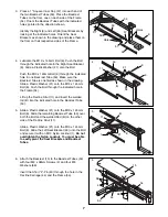
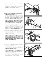
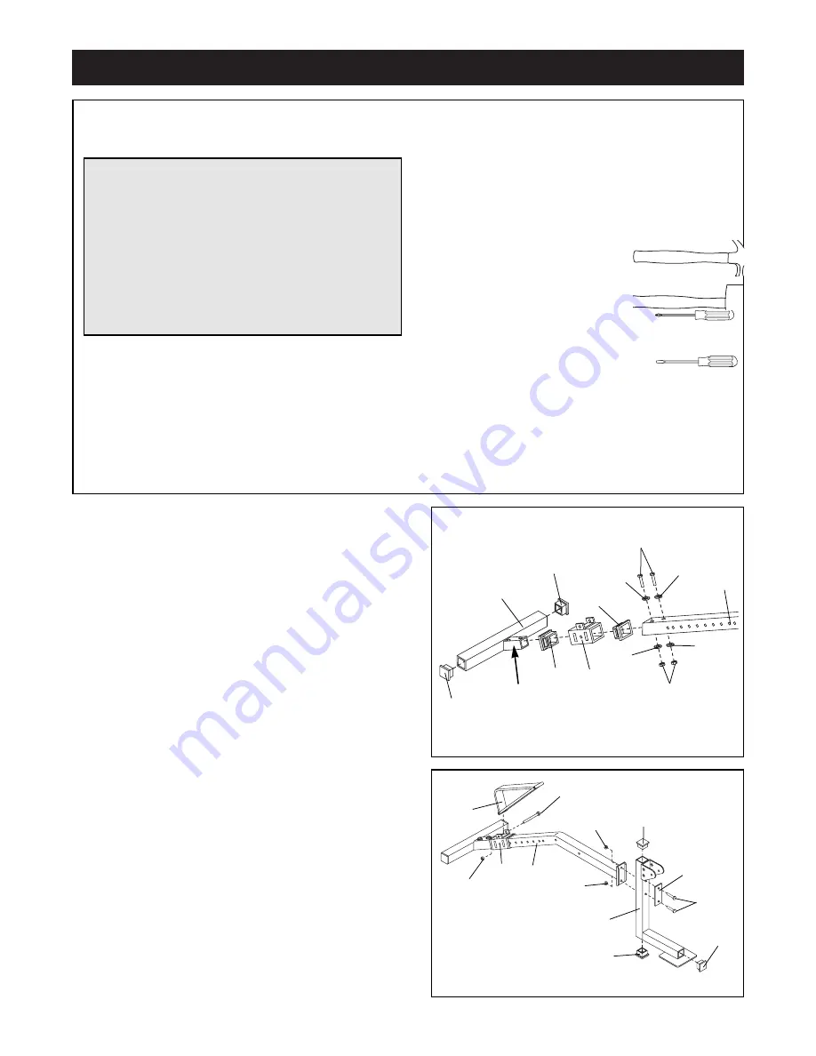
Press a 2Ó Square Inner Cap (17) into each end of
the Stabilizer (20). Press a Carriage Bushing (56) into
each end of the Decline Carriage (44). Slide the
Decline Carriage onto the indicated end of the Frame
(54). 

Slide the Frame (54) onto the bracket (A) on the
Stabilizer (20) and secure it with two M10 x 65mm
Bolts (5), four M10 Washers (6) and two M10 Nylon
Locknuts (1). 

Tighten the Nylon Locknuts until

there is no play between the Frame and Stabilizer.

1

Before beginning assembly, carefully read the
following information and instructions:

¥

Assembly requires two people.

¥

Place all parts in a cleared area and remove the
packing materials. Do not dispose of the packing
materials until assembly is completed. 

¥

Tighten all parts as you assemble them, unless
instructed to do otherwise. 

¥

For help identifying the small parts, use the PART
IDENTIFICATION CHART on page 5.

¥

As you assemble the weight bench, make sure all
parts are oriented as shown in the drawings.  

The following tools (not included) are required
for assembly: 

¥ Two (2) adjustable wrenches

¥ One (1) rubber mallet

¥ One (1) standard screwdriver

¥ One (1) phillips screwdriver

¥ Lubricant, such as grease or petroleum jelly

plus soapy water.

Assembly will be more convenient if you have the
following tools: A socket set, a set of open-end or
closed-end wrenches or a set of ratchet wrenches.

Assembly

Make Things Easier for Yourself!

Everything in this manual is designed to ensure
that the assembly of our products can be complet-
ed successfully by anyone. However, it is impor-
tant to recognize that your new equipment is a
sophisticated product with many small parts and
consequently, the assembly process will take
time. Most people find that by setting aside plenty
of time, and by deciding to make the task enjoy-
able, assembly will go smoothly. 

20

56

56

44

17

54

5

6

6

6

6

1

17

A

2.

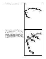
Press a 2Ó Square Inner Cap (17) into each of the
open ends of the Pad Upright (19). 

Attach the Pad Upright (19) to the Frame (54) with
two M8 x 68mm Bolts (38), the Support Plate (16)
and two M8 Nylon Locknuts (13). 

Attach the Decline Strut (11) to the Decline Carriage
(44) with the M10 x 75mm Bolt (72) and an M10
Nylon Locknut (1). 

Do not overtighten the Nylon

Locknut. You must be able to freely pivot the
Decline Strut. 

2

17

38

13

19

13

11

54

44

1

17

72

16

17

Summary of Contents for 660 Weight Bench

Page 1: ...LINE The trained techni cians on our customer hot line will provide immediate assis tance free of charge to you CUSTOMER HOT LINE 1 800 999 3756 Mon Fri 6 a m 6 p m MST Model No PFBE66080 Serial No Wr...

Page 2: ...g is attached to the center of this manual Remove the Part List Exploded Drawing before beginning assembly Table of Contents The decals shown below have been placed on the weight bench If a decal is m...

Page 3: ...luding the barbell on the barbell rack Do not place more than 150 pounds on each weight carriage Do not place more than 150 pounds on the leg lever for normal use 12 Make sure that the cables remain o...

Page 4: ...t read this manual carefully before using the PROFORM 660 Weight Bench If you have additional questions please call our Customer Service Department toll free at 1 800 999 3756 Monday through Friday 6...

Page 5: ...M8 x 68mm Bolt 38 M6 x 16mm Screw 3 M6 Nylon Locknut 2 M6 x 38mm Screw 4 M6 x 61mm Bolt 33 M8 x 70mm Bolt 52 1 2 Spacer 50 1 2 Nylon Locknut 60 M8 x 62mm Bolt 58 M8 Spacer 66 M8 x 14mm Screw 30 Plasti...

Page 6: ...are required for assembly Two 2 adjustable wrenches One 1 rubber mallet One 1 standard screwdriver One 1 phillips screwdriver Lubricant such as grease or petroleum jelly plus soapy water Assembly wil...

Page 7: ...d in the direction shown Identify the Right 9 and Left 46 Seat Brackets by looking at the indicated holes Orient the Seat Brackets as shown in the drawing and place them on the floor on their respecti...

Page 8: ...t overtighten the Nylon Locknut You must be able to freely pivot the Lock Lubricate the M10 x 72mm Bolt 59 Attach the Leg Lever 18 to the bracket C on the Pad Upright 19 with the Bolt and an M10 Nylon...

Page 9: ...o not tighten the Nylon Locknuts yet Attach the Left Base 26 to the Joiner Bracket 27 with two M10 x 65mm Bolts 5 four M10 Washers 6 and two M10 Nylon Locknuts 1 Do not tighten the Nylon Locknuts yet...

Page 10: ...6 and an M10 Nylon Locknut 1 Do not tighten the Nylon Locknut yet Repeat the above steps for the Left Base 26 not shown Make sure the Weight Uprights 41 42 are orient ed exactly as shown 14 Slide a pr...

Page 11: ...me 24 to the right Weight Upright 42 and the right Barbell Upright 41 in the same manner When this is completed tighten all Nylon Locknuts used in the Base the Uprights and the Top Frame see steps 12...

Page 12: ...posi tioned as shown so it will hold the Cable in place 18 19 12 73 45 37 45 42 40 39 35 28 35 24 1 17 Lubricate the welded bolts on the Top Frame 24 and the Left Base 26 Attach a Pulley Bracket 28 to...

Page 13: ...eight Hooks 29 are positioned so they lock into both Barbell Racks 31 at the same time when you turn the Barbell 74 22 23 J 74 30 34 29 31 41 20 Wrap the Cable 45 around a 3 1 2 Pulley 35 in the direc...

Page 14: ...point to which you want your Barbell 74 to go during the exercise Rotate your Barbell until the Barbell Hooks 29 disengage from the Barbell Uprights Perform the exercise as shown in the accompanying E...

Page 15: ...on the leg lever WARNING Always insert the L pin before putting any weight on the backrest LOCKING THE LEG LEVER Some exercises such as sit ups can be performed more comfortably with the Leg Lever 18...

Page 16: ...t included onto the weight tube of one of the Weight Carriages 37 If you are using olympic weights you will need to use a Weight Adapter 48 See assembly step 13 for instructions If the exercise you ar...

Page 17: ...develop your heart and lungs PERSONALIZING YOUR EXERCISE PROGRAM Specifying the exact length of time for each workout as well as the number of repetitions or sets for each exercise is a highly individ...

Page 18: ...this manual can be photocopied and used to schedule and record your workouts List the date the exercises performed the weight plus the numbers of sets and repetitions completed Record your weight and...

Page 19: ...GHT SETS REPS EXERCISE WEIGHT SETS REPS EXERCISE WEIGHT SETS REPS AEROBIC EXERCISE AEROBIC EXERCISE TUESDAY Date WEDNESDAY Date THURSDAY Date FRIDAY Date Make photocopies of this page for scheduling a...

Page 20: ...x 41mm Bolt 35 8 3 Pulley 36 2 Handle with Foam Grip 37 2 Weight Carriage 38 2 M8 x 68mm Bolt 39 2 M10 x 39mm Bolt 40 4 Cable Trap 41 2 Barbell Upright 42 2 Weight Upright 43 2 M10 x 93mm Bolt 44 1 D...

Page 21: ...24 17 55 6 6 6 6 23 6 6 1 6 6 6 1 6 15 57 57 53 68 68 4 4 8 21 14 9 3 3 68 68 11 17 17 20 56 56 44 54 17 63 10 10 10 10 10 10 17 17 17 17 19 67 77 67 65 65 65 65 65 65 50 18 16 49 62 51 12 48 47 56 56...

Page 22: ...d by sufficient proof of purchase All returns must be pre autho rized by ICON This warranty does not extend to any product or damage to a product caused by or attribut able to freight damage abuse mis...

Reviews: